Guidelines to Enhancing the Heart-Rate Monitoring Performance of Biosensing Wearables
要約
In the wearable design process, a key step consists of the opto-mechanical integration of light-emitting and light-sensing elements into biosensing wrist wearables. Selecting components and geometries that minimize crosstalk and maximize signal to noise can significantly impact signal quality. This application note examines the optical and mechanical aspects to be considered for optimal performance. The optical portion focuses on the interaction of light with the skin and blood as well as selection of LEDs and photodetectors. The mechanical portion provides suggestions that increase coupling between the optics and the skin.
Introduction
Wrist-based wearables are giving users more proactive control over their well-being, tracking various physiological parameters during fitness, daily activity, and sleep. The tracking process is conveniently non-invasive, as optical sensors integrated into the devices are used to detect the heart-rate signal and derive the parameters. This technology has been established in the medical sector and is now being transferred to wearable wrist applications.
Optical Sensor Operation
Optical sensors utilize a principle called photoplethysmography (PPG) to measure heart rate. As the heart pumps, the volume of blood transported in the arteries changes. More blood flows through the arteries when the heart expels blood (systolic phase) and less blood flows when the heart draws blood in (diastolic phase). When the blood volume changes between systolic and diastolic heartbeats, it changes the optical absorption coefficient of the arterial layer. Optical illumination of the tissue along with measurement of the transmitted light reveals the absorption change due to the blood volume change and allows the heart-rate pulsatile signal to be recovered.
Transmissive heart-rate measurements are logistically difficult on certain areas of the body, such as the wrist. As a result, reflective measurements are used instead. Reflective heart-rate monitors consist of a light source and a detector arranged in the same plane (Figure 1). The light emitted penetrates the skin, tissue, and blood vessels and is either absorbed, scattered, or reflected. A small portion of the emitted light eventually reaches the photodetector. As the volume of blood in the arteries changes with every heartbeat, the fraction of light absorbed and, subsequently, the strength of the detector signal changes.
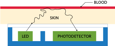
Figure 1. The principle of reflective optical-pulse measurements.
When Light Interacts with Skin
Skin consists of three main layers from the surface: the blood-free epidermis layer (100µm thick), vascularized dermis layer (1-2mm thick), and subcutaneous adipose tissue (1-10mm thick, depending on the body site). Typically, the optical properties of these layers are characterized by absorption (µa) and scattering (µs) coefficients and the anisotropy factor (g).
The absorption coefficient characterizes the average number of absorption events per unit path length of photons traveling in the tissue. The main absorber in the visible spectral range is melanin: blood composed of oxyhemoglobin (Hb), deoxyhemoglobin (HbO2), and lipids. In the IR spectral range, absorption properties of skin dermis are dominated by absorption of water.
Figure 2 presents a planar seven-layer optical model of human skin, including the stratum corneum, the living epidermis (each of the two layers of dermis are divided into two layers, first papillary dermis and superior blood net dermis and second reticular dermis and inferior blood net dermis), and, finally, the subcutaneous adipose tissue layer. Table 1 lists the thickness of the layers, typical ranges of blood, water, and melanin contents, along with refractive indices of the layers.
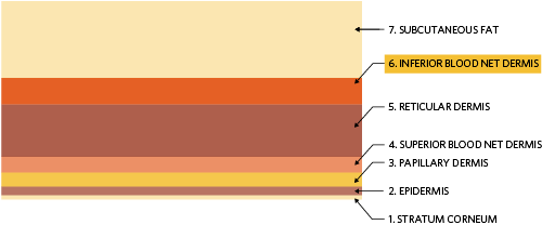
Figure 2. Seven-layer skin model where the first and outermost layer is the stratum corneum and the innermost layer is the subcutaneous adipose tissue or fat layer.
| Layer | Thickness | Volume Fraction | Refractive Index | |||
| t(µm) | θ(blood) | θ(water) | θmel | n | ||
| 1 | Stratum corneum | 20 | 0 | 0.05 | 0 | 1.40 |
| 2 | Epidermis | 80 | 0 | 0.2 | 0.01 – 0.10 | 1.40 |
| 3 | Papillary dermis | 150 | 0.0024 | 0.5 | 0 | 1.39 |
| 4 | Superior blood net dermis | 150 | 0.0060 | 0.6 | 0 | 1.39 |
| 5 | Reticular dermis | 1000 | 0.0024 | 0.7 | 0 | 1.41 |
| 6 | Inferior blood net dermis | 600 | 0.0120 | 0.7 | 0 | 1.41 |
| 7 | Subcutaneous fat | 8000 | 0.0012 | 0.7 | 0 | 1.44 |
As highlighted in Table 1, the heart-rate pulsatile signal originates from the arterial bed lying down in the inferior blood net dermis layer and is the sixth layer in the seven-layer tissue model. The absorption spectrum of this layer can be calculated using the absorption spectra of tissue constituents and its corresponding volume fractions by using the following equation:
µa (λ)= (Sµa,Hb (λ) + (1-S)µa,HbO2 (λ))θ blood + µa,mel (λ)θ mel+ µa,water (λ)θ water + µa,lip (λ)θ lip
where µa,mel, θ mel, µa,water, θ water, µa,lip, θ lip are the absorption coefficients and volume fractions of melanin, water, and lipids, respectively. µa,Hb and µa,HbO2 are the absorption coefficients of oxyhemoglobin and deoxyhemoglobin, and θ blood is the volume fraction of blood. S is the blood oxygen saturation coefficient, typically around 95% in healthy individuals. Using Equation 1 and measured absorption spectra for the tissue constituents [1] the absorption coefficient in the inferior blood net dermis can be calculated as a function of wavelength. Figure 3 plots the results.
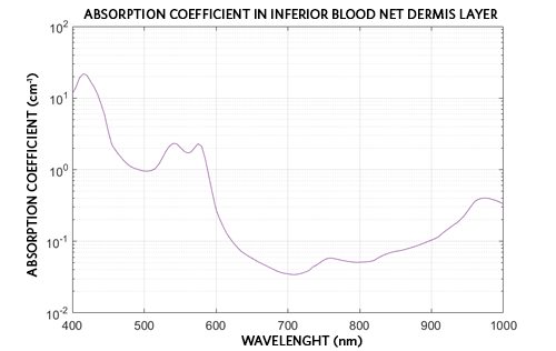
Figure 3. Absorption coefficient in the inferior blood net dermis layer as a function of wavelength.
The peak absorption coefficients correspond to wavelengths around 540nm and 570nm. At these wavelengths the absorption change due to the blood volume change is the greatest, and the photodiode measures the strongest pulsate signal.
Selecting Components
LED Wavelengths and Efficiency
To acquire the best PPG signal, i.e., largest AC heart-rate signal, the LED illumination wavelength should be as close as possible to the absorption peaks of the blood HbO2 at around 540nm and 570nm (Figure 3). However, because of the known "green gap" range in the LEDs’ luminous efficacy around 560nm, commercially available LEDs are very dim at these two desired wavelengths. As such, they are not particularly useful for practical applications where high signal-to-noise ratio (SNR) is required. Therefore, green LEDs emitting around 530nm are utilized in most commercial PPG sensors available on the market.
Maxim Integrated has explored illumination wavelengths at both sides of the green absorption peak, the widely used true-green LEDs at 530nm and yellow LEDs at 590nm. While both wavelengths are available with large luminous efficacy from multiple LED vendors, we have found the OSRAM® PointLED [2] product line to offer the most suitable form-factor for building Maxim wrist PPG sensor wearable prototypes.
Photodiode
One of the most critical component selection choices in a wearable heart-rate monitor is the photodiode. The photodiode is the first stage in the system’s receiving path. There are many photodiode options available in the broad market, so it is important to choose one with high responsivity at key operating wavelengths or ranges thereof. Responsivity is a measure of the electrical output per optical input and is often expressed in current produced per watt of incident radiant power (A/W). A high-responsivity device can detect the small heart-rate signals returning from scattering inside the wrist tissue. Si PIN photodiodes have the largest responsivity in the visible/NIR wavelength range and are available from many manufacturers. Vishay® and OSRAM Si PIN photodiodes are particularly useful for biosensing wrist wearables due to their small form factor [3,4].
Opto-Mechanical Design Considerations
Overview
Designing a good optical PPG solution is very complex and is often underestimated. Let us consider the integration of optical components to make a complete heart-rate monitor for wrist wearables.
Successful integration maximizes both the signal received by the sensor and the signal-to-noise parameter. To increase the signal-to-noise parameter, we can maximize the signal that has penetrated deep enough into the skin to detect a PPG signal while minimizing crosstalk, which is the signal on the sensor from sources other than the PPG signal. Figure 4 depicts a typical opto-mechanical integration design. Here the LEDs and photodiode are encapsulated in a transparent material to provide a moisture barrier and interface between the optical components and the wrist. Barriers between the LEDs and photodiode provide optical isolation, which ensures that only light that has traversed through skin tissue reaches and is detected by the photodiode. The entire assembly protrudes from the bottom of the wrist band to ensure tight contact with the skin.
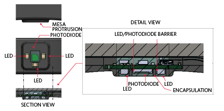
Figure 4. Typical opto-mechanical design.
Encapsulation
As with any wrist wearable design, customers need some sort of sealant for the optical design. This sealant provides waterproofing properties and also increases the signal received by the sensor. A sealant with an index of refraction close to that of human skin (~1.4) can minimize transmission losses due to Fresnel reflections. Additionally, a sealant that provides some “give” can increase the contact area and pressure with the skin. Silicones are commonly used sealants. Table 2 provides good silicone candidates for an encapsulation material and their characteristics.
| Encapsulation Comparison Table | |||||||
| Manufacturer | Product Name | Color | Viscosity (cP) | Index of Refraction | Transmission (3.2mm Thick) | Hardness | Comments |
| Dow Corning | Sylgard 184 Silicone Elastomer | Colorless | 3,500 | 1.4118 at 589nm 1.4225 at 632.8nm |
97% at 532nm 96% at 880nm |
Durometer Shore 43 | High transmission, flexible elastomer |
| Dow Corning | EI-1184 Optical Encapsulant | Clear | 5,300 | 1.42 at 632.8nm | 93% at 380nm 94% at 450nm 94% at 760nm |
Durometer Shore A 61 | Cures to flexible elastomer, cure time can be decreased with heat |
| Dow Corning | MS-1002 Moldable Silicone | Optically clear | 26,250 | 1.41 at 632.8nm | 89% at 380nm 91% at 450nm 94% at 760nm |
Durometer Shore A 72 | Moldability allows for more complex designs |
| Dow Corning | MS-1003 Moldable Silicone | Optically clear | 42,300 | 1.41 at 632.8nm | 91% at 380nm 92% at 450nm 93% at 760nm |
Durometer Shore A 51 | Moldability allows for more complex designs |
| Dow Corning | MS-4002 Moldable Silicone | Optically clear | 25,000 | 1.42 at 632.8nm | 89% at 380nm 92% at 450nm 93% at 760nm |
Durometer Shore A 84 | Moldability allows for more complex designs |
| Dow Corning | IMS-4007 Moldable Silicone | Optically clear | 10,500 | 1.41 at 632.8nm | 91% at 380nm 93% at 450nm 94% at 760nm |
Durometer Shore A 70 | Moldability allows for more complex designs |
Crosstalk-Suppressing Features – Light Barriers
Crosstalk consists of signal incidents on the photodiode that have not traversed through any skin layers. High levels of crosstalk drown out the pulsating heart-rate signal, rendering the wearable monitor incapable of effectively measuring PPG. Thus, crosstalk between the LED emission and the photodetector should be minimized for optimal performance. To maintain a low level of crosstalk, physical absorbing light barriers can be used. An example barrier is shown in the detail view in Figure 4
Mesa – Increasing Contact with Skin
Crosstalk consists of signal incidents on the photodiode that have not traversed through any skin layers. High levels of crosstalk drown out the pulsating heart-rate signal, rendering the wearable monitor incapable of effectively measuring PPG. Thus, crosstalk between the LED emission and the photodetector should be minimized for optimal performance. To maintain a low level of crosstalk, physical absorbing light barriers can be used. An example barrier is shown in the detail view in Figure 4
Separation Distance Between LEDs and the Photodiode
When developing a reflectance heart-rate monitor, it is important from a design standpoint to determine the ideal separation distance between the LEDs and the photodiode. When selecting the distance, ensure that PPG signals with both maximum and minimum pulsatile components can be detected. These pulsatile components depend not only on the amount of arterial blood in the illuminated tissue but also on the systolic blood pulse strength in the peripheral vascular bed.
Two techniques are available to enhance the quality of the plethysmogram signal. One technique involves using a large LED driving current, which increases the effective penetration depth of the incident light using the higher, light intensity. For a given LED-photodiode separation, using higher levels of incident light results in illuminating a larger pulsatile vascular bed. As a result, the reflected plethysmogram contains a larger pulsate signal component. However, in practice, the LED driving current is limited by the manufacturer to a specified maximum power dissipation. The alternate method is to place the photodiode close to the LEDs. However, if the photodiode is too close to the LEDs, the photodiode becomes saturated by the large non-pulsatile component obtained by the multiple scattering of incident photons by the blood-free stratum corneum and epidermal layers in the skin. For a constant LED intensity, the total light detected by the photodiode decreases roughly exponentially as the radial distance between the LEDs and the photodiode is increased. In other words, the effect of LED/photodiode separation on the reflected pulse amplitude of both green and yellow plethysmograms is decreased with the increase in separation. Thus, there is a trade-off in the selection of a particular separation distance. Placing the photodiode farther apart from the LEDs can result in a plethysmogram with a larger pulsate signal component. However, this approach requires a higher LED driving current to overcome absorption due to increased optical path length.
Simulated Comparison of LED-Photodiode Separation
To evaluate the effects of the LED-photodiode separation, let us define two key figures of merit for PPG measurements: collection efficiency (CE) and perfusion index (PI).
CE is the fraction of power back on the photodiode for a given LED output. This optical signal incident on the photodiode is converted into current and consists of a large constant DC and a small variable AC component. The DC component contains no heart-rate information, while the AC corresponds to the pulsing arterial blood [5], as shown in Figure 5.
PI, defined as the ratio of AC to DC, is the ratio of the pulsatile blood flow to the non-pulsatile static blood flow in the peripheral tissue. The PI provides an indication of the pulse strength at the sensor site. The higher the PI, the better the performance. PI depends on the path length through the inferior blood net dermis, l , and the change in the absorption coefficient, Δµ, which are both wavelength dependent.
PI= AC/DC = lΔµ
PI varies depending on skin type, motion artifacts, ambient light, fitness levels, and fat content in the body. In wrist-based applications, PI values range from 0.02% for a very weak pulse to 2% for an extremely strong pulse.
Since a good PPG signal is a tradeoff between total power and PI, the figure of merit to examine when determining the optimal LED/photodiode spacing is the product of the CE and PI (CE × PI). This quantity is proportional to the AC signal strength and a higher CE × PI value corresponds to a greater AC signal.
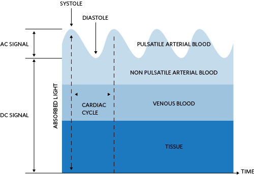
Figure 5. Light absorption diagram of the skin and corresponding DC and AC levels.
Ray trace simulation is used to determine the effects of LED-photodiode separation on PI. The simulation uses a Monte Carlo method to trace optical rays propagating in complex, inhomogeneous, randomly scattering, and absorbing media. The geometry simulated consists of 1mm × 1mm active area detectors distanced 1mm to 10mm from a Lambertian emitting LED. The seven-layer model of the skin is placed above the LED and detectors. Figure 6 shows the simulation setup.
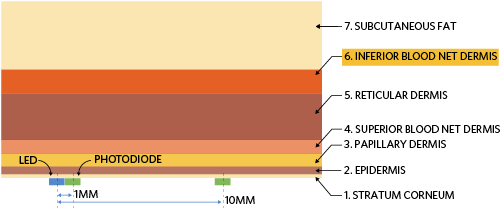
Figure 6. Simulation setup to determine optimal LED-photodiode separation.
The simulation determines the collection efficiency for a given wavelength and LED-photodiode spacing. Post-processing the simulation results yields the corresponding path length in the inferior blood net dermis layer. Knowing the path length, l, and change in the absorption coefficient, Δµ, the PI can be calculated by Equation 2. The simulation results are given in Figure 7, Figure 8, and Figure 9 for 530nm, 560nm, 574nm, and 590nm. It is evident in Figure 9 that up to 3mm LED-photodiode separation, 574nm yields the highest PPG signal. Above 3mm separation, the 590nm PPG signal quality outperforms other wavelengths.
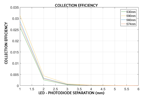
Figure 7. Collection efficiency as a function of LED-photodiode spacing.
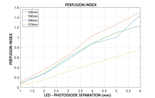
Figure 8. Perfusion index as a function of LED-photodiode spacing.
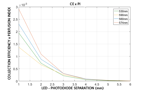
Figure 9. Product of the CE and the PI as a function of LED-photodiode spacing.
Maxim offers ICs that are suited for wearable, wrist-based heart-rate detection applications. The MAX86140/MAX86141 devices are complete, integrated optical data acquisition systems, ideal for optical pulse oximetry and heart-rate detection applications. Both include high-resolution optical readout, signal-processing channels with ambient-light cancellation, and high-current LED driver DACs to form a complete optical readout signal chain. The MAX86140 consists of a single optical readout channel, while the MAX86141 has two optical readout channels that can operate simultaneously. The MAX86140/MAX86141 have three LED drivers and are well suited for a wide variety of optical-sensing applications.
While the MAX86140/MAX86141 devices take care of the data acquisition, the designers must decide how to integrate the LEDs and photodetector into their industrial designs. This application note outlined how reflective heart-rate monitors operate, including the interaction with the skin and the selection of the light-emitting and sensing elements.
Summary
Thanks to small, powerful analog front-end electronics, designers can now more easily incorporate biosensing functionalities such as heart-rate monitoring into consumer wrist wearables. Careful optical component selection and opto-mechanical integration into the end design are big factors affecting the performance of these wearable sensors. When selecting the optical components, carefully consider the wavelength and luminous efficacy for the LED, wavelength, and responsivity of the photodiode. For the highest quality signal, important considerations include encapsulation, crosstalk-suppressing barriers, and careful determination of LED-photodiode separation.
Trademarks
OSRAM is a registered trademark of Osram GmbH.
A similar version of this application note originally appeared in Sensors Online on June 21, 2018.
{{modalTitle}}
{{modalDescription}}
{{dropdownTitle}}
- {{defaultSelectedText}} {{#each projectNames}}
- {{name}} {{/each}} {{#if newProjectText}}
-
{{newProjectText}}
{{/if}}
{{newProjectTitle}}
{{projectNameErrorText}}


