Enhancing Industrial Motor Control Performance Utilizing Digital Isolator Technology
Enhancing Industrial Motor Control Performance Utilizing Digital Isolator Technology
2014年11月01日
Isolating users and sensitive electronics has been a key consideration in motor control systems. Safety isolation protects users from harmful voltages, while functional isolation is focused on protecting equipment and components. Motor control systems may contain a variety of isolated components in drive circuitry (isolated gate drivers), in sense circuitry (isolated ADC, amplifiers, sensors), or in communication circuitry (isolated SPI, RS-485, standard digital isolators), and careful selection of these components is vital, not only for safety reasons, but for optimizing performance as well.
While an important system consideration, isolation is not without its rawbacks: increased power, delays in transferring data across the isolation barrier, and additional system cost. System designers have traditionally turned to optocoupler-based solutions, which for many years were the de facto choice for system isolation. Digital isolators based on magnetic (transmission by transformer) methods have for the last decade provided a viable and often superior alternative, and when considered at a system level, may offer benefits not always recognized by system designers.
This article will look at the two solutions for isolation requirements, with particular focus on the improved performance in terms of delay timing that magnetic-based isolation provides, and the consequent system-level benefits that accrue in motor control applications.
Isolation Methods
Optocouplers use light as the main transmission method, as shown in Figure 1. The transmit side consists of an LED, in which high signals turn the LED on and low signals turn it off. On the receive side, a photodetector is used to convert the received light back into an electrical signal. Isolation is provided by the mold compound between the LED and the photodetector, but may also be enhanced with an additional isolation layer, typically polymer based.

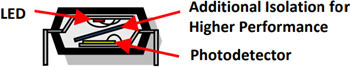
Figure 1. Optocoupler Structure
One of the biggest drawbacks associated with optocouplers is that as the LEDs age the emission characteristics drift, creating an additional issue that designers must take into consideration. Degradation of the LED results in timing drift over time and with temperature. As a result, propagation and ride/fall times are affected, complicating designs especially in the context of the issues dealt with later in this article.
Optocouplers also suffer in terms of performance scalability. In order toincrease data rates, parasitic capacitances, inherently found in optocouplers, must be overcome, which requires an increase in power consumption. The parasitic capacitance also provides a coupling mechanism that results in poorer CMTI (common-mode transient immunity) performancefor optocoupler-based isolators compared to their competitors.
Magnetic (transformer-based) isolators have been used in high volume applications for over a decade and are a credible alternative to optocouplers. These are based on standard CMOS technology, and use magnetic transmission schemes with isolation layers comprised of polyimide or silicon dioxide, as shown in Figure 2. Low levels of current are pulsed through a coil, creating a magnetic field, which passes through the isolation barrier and induces a current in a second coil on the other side of the barrier. Since they use standard CMOS structures, they offer significant advantages in terms of power and speed, and in addition, eliminate the lifetime variance issues associated with optocouplers. Also, due to the lower parasitic capacitances present in transformer-based isolators, they offer better CMTI performance than optocoupler-based isolators.

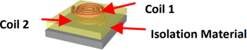
Figure 2. Magnetic Transformer Structure
Transformer-based isolators also allow the use of common processing blocks, which prevent spurious inputs from being transmitted, and advanced transmission encode/decode mechanisms. This allows bidirectional data transfer, the use of different encoding schemes to optimize power vs. transfer rates, and faster and more consistent transfer of important signals across the isolation barrier.
Comparison of Delay Characteristics
One key but often underrated characteristic of all isolators is their propagation delay. This measures the length of time it takes a signal to pass through the isolation barrier in either direction, as it can be a drive signal or a fault detection signal. Propagation delay varies significantly from technology to technology. While typical delay values are often provided, a particular concern for system designers is maximum delay, which is the key specification for consideration when designing motor control systems. Table 1 gives an example of the propagation delay and delay skew values associated with optocoupler- and magnetic-based isolated gate drivers.
| Isolator Type | Max Propagation Delay | Propagation Delay Skew |
| Optocoupler | Up to 700 ns | 200 ns |
| Magnetic | 60 ns | 12 ns |
As Table 1 shows, there is a significant advantage to magnetic-based isolation in terms of both maximum delay and the repeatability of the delay (the skew). This allows motor control designers to design with much more confidence, reducing the need to add margin-to-timing specifications to cater for gate driver characteristics. This has very important implications for both performance and safety in motor control systems.
System Implications for Motor Control Systems
A typical 3-phase inverter used in ac motor control applications is illustrated in Figure 3. The inverter is supplied from a dc bus, typically generated directly from the ac mains through a diode bridge rectifier and capacitive or inductive capacitive filter. In the majority of industrial applications, the dc bus voltage is in the range of 300 V to 1000 V. A variable voltage, variable frequency 3-phase sinusoidal ac voltage is generated at the motor terminals by switching power transistors T1 to T6 in a pulse-width modulation (PWM) scheme typically at a frequency of 5 kHz to 10 kHz.

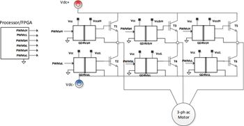
Figure 3. Three-Phase Inverter in a Motor Control Application
PWM signals, such as PWMaH and PWMaL, are generated within the motor controller, generally implemented in a processor and/or FPGA. These signals are generally low voltage signals referenced to the processor ground rail. In order to turn on and turn off the power transistors correctly, the logic level signals must be amplified in voltage level and current source capability. They must also be level shifted so that they are ground referenced to the relevant power transistor emitter. Depending on the processor location within the system, they may also require safety level insulation.
The gate drivers, such as GDRVaL and GDRVaH in Figure 3, carry out these functions. Each gate driver IC will require a primary side power supply voltage referenced to the processor ground and a secondary side supply referenced to the transistor emitter. The secondary side supply will need to have a voltage level capable of turning on the power transistors (typically 15 V), and sufficient current drive to charge and discharge the transistor gates.
Inverter Dead Time
Power transistors have a finite switching time, and hence a blanking or dead time must be inserted in the pulse-width modulation waveforms, as illustrated in Figure 4, between the high-side and low-side transistors. This is in order to prevent both being accidentally on at the same time, hence short circuiting the high voltage dc bus with consequent risk of system failure and/or damage. The length of the dead time is determined by two factors—transistor switching time and gate driver propagation delay mismatch (including any drift in the mismatch). In other words, the dead time must account for any difference in propagation time of the PWM signals from processor to transistor gate between high- and low-side gate drivers.

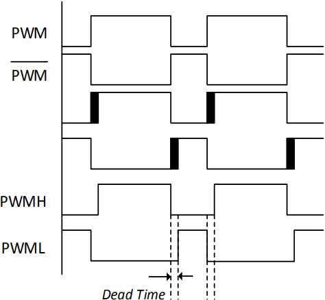
Figure 4. Dead Time Insertion
The effect of the dead time is to distort the average voltage applied to the motor, especially at low speed. The dead time, in effect, injects an approximately constant magnitude error voltage equal to
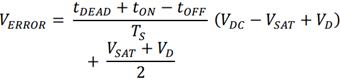
Where VERROR is the error voltage, tDEAD is the dead time, tON and tOFF are the transistor turn on and turn off delay times, and TS is the PWM switching period; VDC is the dc bus voltage, VSAT is the on state voltage drop of the power transistor, and VD is the conduction voltage of the diode.
The error voltage changes sign when the current in a phase leg changes direction, and so, step changes occur in the motor line-to-line voltages at the points where line currents cross zero. This creates harmonics of the sinusoidal fundamental voltage, which in turn, generate harmonic currents in the motor. This is a particular problem for larger low impedance motors used in open-loop drives, where the harmonic currents can be significant, resulting in low speed vibration, torque ripple, and harmonic heating.
The impact of the dead time on distortion of the motor output voltage is at its worst for the following conditions:
- High dc bus voltage
- Long dead time
- High switching frequency
- Low speed operation, especially in open-loop drives where no compensation is added by a control algorithm
Low speed operation is important because it is in this mode that the applied motor voltages are very low in any case, and the error voltage from dead time can be a significant fraction of the applied motor voltage. Moreover at low speed, any induced torque ripple has a more detrimental impact since the filtering effect of system inertia at higher speeds is not available.
Of all of these parameters, the length of the dead time is the only one that can be impacted by the isolated gate driver technology. Some of the dead time length is determined by the switching delay times of the power transistors, but the remainder is a function of the propagation delay mismatch. In this context, optical isolators are at a significant disadvantage to magnetic isolation technology.
Application Example
In order to illustrate the impact of dead time on motor current distortion, results from a 3-phase, inverter-based, open-loop motor drive are illustrated. Magnetic isolators from Analog Devices (ADuM4223) are utilized for the inverter gate drivers, directly driving IRG7PH46UDPBF 1200 V IGBTs from IR. The dc bus voltage is 700 V. The inverter is driving a 3-phase induction motor in open-loop V/f control mode. The line-to-line voltage and the phase currents are measured using resistive dividers and shunt resistors respectively, in conjunction with isolated ∑–∆ modulators, again from Analog Devices (AD7403). The single-bit data stream from each modulator is fed to the sinc filters of the control processor (ADSP-CM408 from Analog Devices), where the data is filtered and decimated to produce a precision representation of the voltage and current signals.
Measured line-to-line voltage from the sinc digital filter output is shown in Figure 5. The actual line-to-line voltage is a high frequency switching waveform at 10 kHz, but this is removed by the digital filter, allowing the lower frequency components of interest to be visualized. The consequent motor phase current is shown in Figure 6.

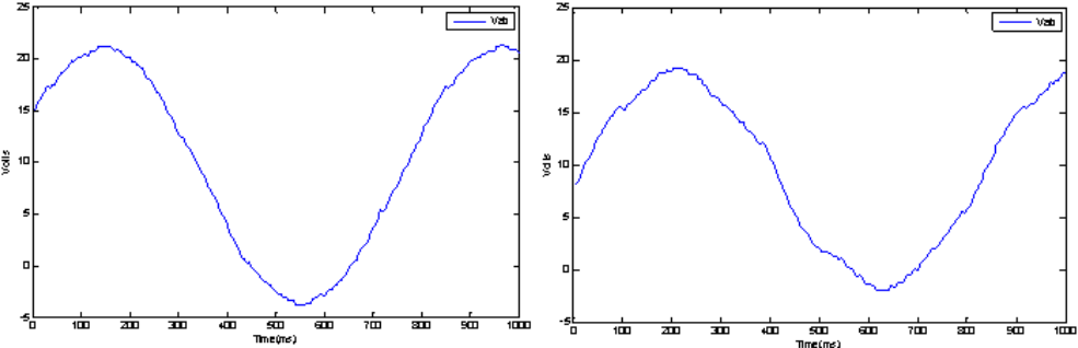
Figure 5. Measured Line-to-Line Motor Voltage at (l) 500 ns Dead Time, (r) 1 µs Dead Time

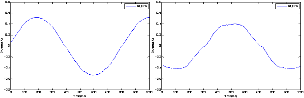
Figure 6. Measured Motor Current at (l) 500 ns Dead Time, (r) 1 µs Dead Time
With the ADuM4223 gate drivers the propagation delay mismatch is 12 ns, so it is possible to use the absolute minimum dead time required for IGBT switching. In the case of the IR IGBTs, the minimum dead time can then be set to 500 ns. It is clear from the figure on the left, that voltage distortion in this case is minimal. Likewise, the phase current is very sinusoidal, which will result in minimal torque ripple. The plots on the right indicate line-to-line voltage and phase current with the dead time increased to 1 µs. This value is more representative of what would be required for optically coupled gate drivers, due to their higher propagation delay mismatch and drift. The increase in distortion of both the voltage and consequent current are evident. The induction motor used in this case is a relatively small, high impedance machine. In higher power end applications, the induction motor impedance will typically be much lower, leading to increased motor current distortion and torque ripple. Torque ripple has a detrimental effect in many applications—for example, reduced ride comfort in elevators, or bearing and coupling wear in mechanical systems.
Overcurrent Turn Off
Another important issue for modern gate drivers is the speed at which a turn off command from the processor can be implemented at the IGBT. This is important in the context of overcurrent shutdown, where the overcurrent detection is not part of the gate driver itself, but where it is implemented as part of the sensing and filtering circuitry. An additional pressure in this area is the reduced short-circuit withstand time of higher efficiency IGBTs. The trend in IGBT technology is for this to reduce from the industry standard 10 µs to 5 µs, and even lower. As shown in Figure 7, the overcurrent detection circuitry will typically take several microseconds to latch the fault—with moves to reduce this detection time to accommodate the overall trend. The other main element in the path is the propagation delay from processor/FPGA output to the IGBT gate (the gate driver). Once again, magnetic isolators provide a significant advantage over optical devices, in that the propagation delay is effectively a nonfactor due to its very low value, typically in the region of 50 ns. By contrast, optocouplers have propagation delays in the region of 500 ns, which represent a significant proportion of the overall timing budget.

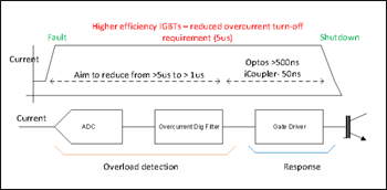
Figure 7. Fault Shutdown Timing
The gate driver turn off timing is illustrated from the motor control application in Figure 8 where the turn off command from the processor is shown followed by the IGBT gate emitter signal. The total delay from commencement of the turn off signal to the point where the IGBT gate drive signal is near zero is only 72 ns.

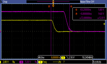
Figure 8. Overcurrent Turn Off Gate Driver Timing
Summary
With increasing focus on system performance, efficiency, and safety, motor control architects are faced with an ever more complicated task in designing robust systems. While optocoupler-based gate drivers have been the traditional choice, transformer-based solutions provide not only advantages in terms of power, speed, and stability over a lifetime, they also, as this article has outlined, provide significant advantages in terms of system performance and safety due to reduced signal delay. This allows designers to confidently reduce dead time, improving system performance while still preventing high-side and low-side switches being on concurrently. In addition, it allows faster response to system commands and errors, again enhancing system reliability while improving safety. These advantages in position transformer-based isolated gate drivers as a leading choice for motor control system design, suggest system designers should strongly consider component delay as a key requirement in their next projects.
著者について
Dara O'Sullivanは、アナログ・デバイセズのソフトウェア・システム・ディレクタです。産業用エッジ/モーション/ロボット・ビジネス・ユニットに所属。産業用モーション制御の分野を対象とした電力変換、制御、監視が専門です。2001年より、研究、コンサルティング、業界における様々な役職といった側面から産業用のアプリケーションや再生可能エネルギーのアプリケーションに取り組んできました。アイルランドのユニバーシティ・カレッジ・コークで工学分...
Maurice Moroney は、アナログ・デバイセズの絶縁型電力変換ポートフォリオのマーケティング・マネージャで、主にモーター・コントロール、自動車、エネルギーの各アプリケーションで絶縁型ゲート・ドライバと電圧/電流検出を担当しています。以前は、消費者、工業、および自動車業界を対象としたマーケティング/アプリケーションを担当していました。Maurice は、アイルランドのリメリック大学で電子工学の学士号(2000 年)と経営学の修士号(...
この記事に関して
産業向けソリューション
最新メディア 21