要約
Infrared cameras are key in automobile driver monitoring systems. A typical power management solution is based on a nonsynchronous buck IR-LED controller that drives an external MOSFET and has a recirculating diode that can’t reach the necessary levels of efficiency and compactness. On the other hand, a highly integrated, synchronous buck IR-LED driver achieves the goals of minimum heat dissipation with a small BOM, enabling compact solutions that operate without overheating.
Introduction
Driver monitoring systems (DMS) are becoming common in modern automobiles. Infrared (IR) cameras, utilizing an IR-LED in combination with a photo sensor, help recognize the hazardous microsleep that can affect motorists. DMS is also an enabling technology for the advancement of autonomous vehicle (AV) driving. In situations where the driver needs to take back control from the car, the monitoring system will give the driver adequate time to react.
All these functions and their associated electronics must fit seamlessly inside the car, which creates the need for flexible, small, and efficient solutions. They must also be able to cope with harsh automobile electrical environments. In this design solution, we review an IR camera system (Figure 1) and discuss the shortcomings of a typical solution. Subsequently, we present an IR-LED driver IC that is flexible, compact, and efficient while interfacing directly to the car battery.
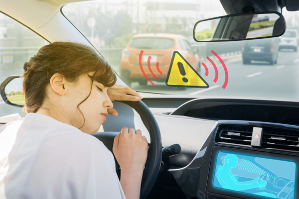
Figure 1. Driver monitoring system in action.
The Infrared Advantage
Some key advantages of infrared light are its invisibility to the human eye and its ability to workday and night. In addition to DMS, IR cameras can also detect and classify pedestrians in darkness, through most fog conditions, and are unaffected by sun glare, delivering improved situational awareness that results in more robust, reliable, and safe ADAS and AV solutions. Other ADAS applications include seat occupancy recognition, night vision systems, short-range detection of surroundings, and monitoring drivers' blind spots.
Infrared Camera
Figure 2 shows the main elements of an infrared camera. The IR-LED illuminates the target. The reflected light is collected by the image sensor (CCD or CMOS photo diode) and processed by the vision processor to determine the response to the situation at hand.
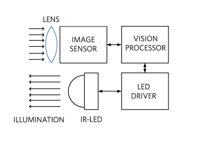
Figure 2. IR-LED camera for DMS.
Buck LED Driver for DMS
The LED driver controls the IR light intensity and strobes it at the right frequency and duty cycle. Ideally it must work directly off the 12V battery and cope with the harsh automotive environment.
Vehicles that employ start/stop technology experience large battery voltage dips when the engine starts, causing the battery voltage to droop well below the typical 12V. Starting from cold conditions (cold-crank), the battery can dip as low as 4.5V. Disconnecting the battery from the alternator during operation results in large voltage transients (dump) up to 60V.
The automotive environment is also subject to electromagnetic interference (EMI) due to both external and internal sources. The “arc and spark” noise that comes from ignition components, motors, and similar pulse-type systems affects the supply voltage rails by producing disruptive undervoltages or overvoltages. The IR-LED buck converter, with its fast switching waveforms, should be able to mitigate any contribution to this noisy environment.
Given the typical forward voltage for an IR-LED diode of 2.4V and a forward current of 1A, a well-designed buck LED driver has enough headroom to be directly connected to the battery without the need for voltage boosting. It must also withstand dump voltage and introduce minimum electromagnetic noise.
Typical High-Power Buck IR-LED Driver Solution
A typical buck IR-LED driver solution is shown in Figure 3. It utilizes an n-channel transistor (typical RDS(ON) = 0.3Ω), and a nonsynchronous architecture that relies on the Schottky diode D for current recirculation. The latter is a sure sign of an inefficient implementation.
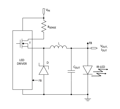
Figure 3. Typical nonsynchronous buck IR-LED driver.
Consider the typical automotive case in which the input voltage is the car's 12V battery and the output is the forward voltage of an IR-LED diode (2.4V at 1A). Here the buck converter duty cycle is only 20%. This means that the MOSFET in Figure 3 conducts only for 20% of the time (0.3Ω at 1A = 0.3W), while the Schottky (0.5V at 1A = 0.5W) conducts for 80% of the time. The total power dissipated in the power train is 0.46W, mostly due to the Schottky diode. After accounting for switching and other losses, this solution barely reaches an efficiency of 80%.
Integrated Synchronous Rectification Solution
As an example, the MAX20050 synchronous buck LED driver is an ideal solution (Figure 4). The device includes a unique spread-spectrum mode that reduces EMI at the switching frequency and its harmonics. With its 4.5V to 65V input supply range, the IC can easily operate under start/stop conditions and cold-crank. It can withstand battery load dump, making it ideal as the front-end buck converter connecting the IR-LED driver directly to the car battery.
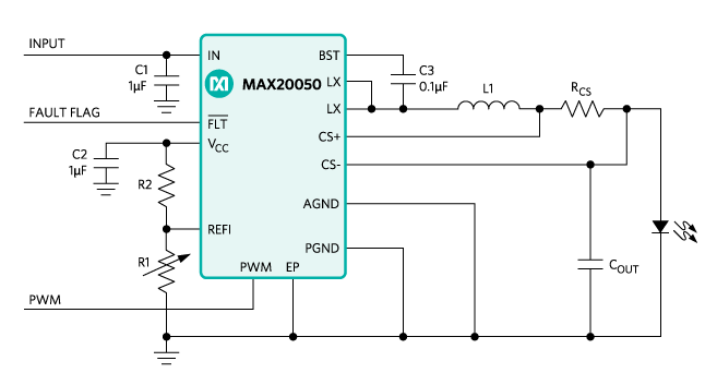
Figure 4. IR-LED driver integrated, synchronous solution.
High Efficiency
The fully synchronous, 2A step-down converter integrates two low RDS(ON) 0.14Ω (typ) n-channel MOSFETs, assuring minimum Ohmic losses. Here, 0.14Ω RDS(ON) resistances will produce losses of only 140mW, one third of the previous case. This solution can easily achieve high efficiency. In Figure 5, the synchronous solution achieves peak efficiency of 86% at 2.1MHz and 92% at 400kHz! Increasing the frequency to 2.1MHz reduces the BOM size at the expense of a few percentage points of efficiency while avoiding interference within the AM band.
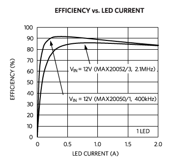
Figure 5. Efficiency vs. size tradeoff.
Small Size
The high level of integration of this solution yields minimal PCB area occupation. Figure 6 shows a nonsynchronous buck converter IC requiring an external Schottky diode that occupies a PCB area almost double (+78%) that of the single-chip solution.
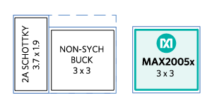
Figure 6. Size comparison of nonsynchronous vs. synchronous buck ICs.
Flexibility
For maximum flexibility, a family of IR-LED drivers (Table 1) offers two operation frequencies to address efficiency-vs-size tradeoffs and to provide internal-vs-external loop compensation for dynamic response optimization.
| IR-LED Drivers | Swiching Frequency | Loop Compensation |
| MAX20050 | 400kHz | Internal |
| MAX20051 | 400kHz | External |
| MAX20052 | 2.1MHz | Internal |
| MAX20053 | 2.1MHz | External |
The devices are specified for operation over the full -40°C to +125°C temperature range and are available in thermally enhanced 12-pin (3mm × 3mm) TDFN and 14-pin (5mm × 4.4mm) TSSOP packages with an exposed pad.
For higher power, the MAX20078 synchronous buck LED controller can be utilized. For higher voltage applications, the MAX20090 high-voltage, high-brightness LED controller is an excellent choice.
Conclusion
Driver monitoring systems are appearing more frequently in modern automobiles. They must fit seamlessly within the automotive electronic system, creating the need for flexible, small, and efficient solutions. They must also cope with harsh automobile environments. We reviewed the IR camera system and discussed the shortcomings of a typical solution. Finally, we presented an IR-LED driver IC that is flexible, compact, efficient, has low EMI, and interfaces directly to the car battery.
A similar version of this design solution originally appeared in Electronic Products on February 10, 2019.
{{modalTitle}}
{{modalDescription}}
{{dropdownTitle}}
- {{defaultSelectedText}} {{#each projectNames}}
- {{name}} {{/each}} {{#if newProjectText}}
-
 {{newProjectText}}
{{/if}}
{{newProjectText}}
{{/if}}
{{newProjectTitle}}
{{projectNameErrorText}}
最新メディア 20


