Backhaul Alternatives for 4G/5G HetNet Base Stations Part 1 - Equipment Trends and Solution Toolbox
要約
Seeking mobile backhaul alternatives, Wireless Service Providers (WSP) have adopted a “solution toolbox” to meet backhaul capacity demand in 4G/5G cellular base stations. The WSP solution toolbox includes both wired and wireless transport technologies. For many backhaul deployment scenarios, the Service Providers recognize that wireless transport has significant advantages over wired media alternatives. However, wireless technologies present some unique design challenges. Overcoming these challenges requires specialized RFIC devices that can help shrink equipment size, lower operating power, improve dynamic performance, and extend mean-time-between-failures (MTBF).
Introduction
This application note is Part 1 of a two-part series that discusses wireless mobile backhaul systems deployed in 4G and 5G heterogeneous networks (HetNets). The application notes present different equipment categories and emerging equipment segment trends. They also discuss microwave, millimeter wave, and sub-6GHz radio applications in small-cell and macro-cell base stations. The application notes explore the role of radio frequency (RF) analog integration and high-performance RF building blocks, with a focus on point-to-point microwave systems and broadband satellite systems.
Part 1 of this series takes a look at mobile backhaul market drivers, equipment trends, and the toolbox of different backhaul solutions deployed across cellular radio-access networks. It discusses equipment segmentation and equipment configurations. This part also presents considerations and selection criteria to help guide the backhaul-solution decision process.
Part 2 of the series focuses on point-to-point microwave and broadband satellite systems typically used for wireless backhauling in macro-cell and small-cell base stations. The second part discusses techniques to improve radio-link spectral efficiency and radio lineup scenarios. Part 2 also explores the role of RF analog integration and RF building blocks, along with relevant solutions.
Mobile Backhaul: Transporting Voice and Data Traffic
Throughout the cellular network, wireless service providers provision mobile backhaul to transport voice and data traffic between the access layer and core network (Figure 1). Wired transport and wireless transport are the two types of mobile backhaul deployed within the radio access network (RAN). At the HetNet access layer, the wireless RAN equipment includes macro-cell base stations, small-cell base stations, and distributed antenna systems (DAS). With the advent of heterogeneous networks, mobile backhaul has become a critical RAN element for air-interface standards such as 4G LTE-Advanced (LTE-A) and emerging 5G New Radio (5G-NR).
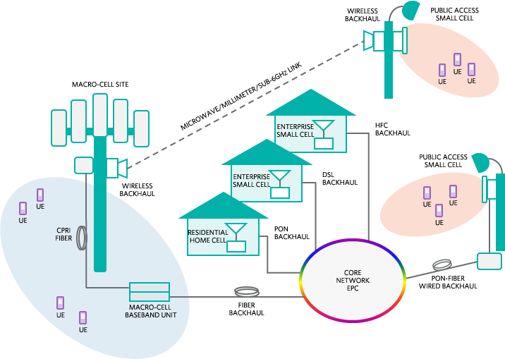
Figure 1. In emerging 4G/5G HetNets, mobile backhaul is a critical RAN element.
Cellular networks have evolved into heterogeneous networks where different classes of small-cell base stations and DAS installations are coordinated to work in concert with macro-site base stations. A HetNet topology improves cellular network capacity and coverage, supporting the exponential growth in mobile traffic. Consequently, HetNets deliver ubiquitous connectivity with exceptional quality of experience for 4G/5G mobile users. Backhaul brings together mobile broadband users, small cells, DAS, macro cells, and the core network.
Wireless Backhaul HetNet Requires High Throughput in Urban Environments
The emergence of HetNet radio access has created a need for diverse wired and wireless mobile backhaul solutions. Small-cell installations include a variety of indoor and outdoor non-telecom asset sites. Examples include street lamp posts, utility poles, and other urban structures, also called "street furniture." These sites can be found throughout corporate campuses and public spaces. Based on the installation scenario, each small-cell site has specific requirements for power sourcing, power budget, and backhaul transport. Meanwhile, conventional macro-cell base stations continue to upgrade network capacity, further driving demand for high-throughput backhaul.
Given the breadth and velocity of planned HetNet deployments, not to mention the broad range of installation scenarios, it's no wonder that WSPs are employing a "toolbox" approach to meet backhaul demands. A toolbox approach includes different wired and wireless transport technologies to address diverse backhaul requirements. Wireless technology itself is an important tool here, providing many advantages over wired technologies. However, wireless solutions also present unique design challenges: the need for spectrally efficient radio links, low operating power, small form factor, and environmentally hardened high-reliability equipment. RF analog integration can help overcome some of these challenges, as shown in Figure 2. Here, a typical microwave radio transmitter relies on RF analog integration and RF building-block solutions to shrink size, lower power, and improve dynamic performance.
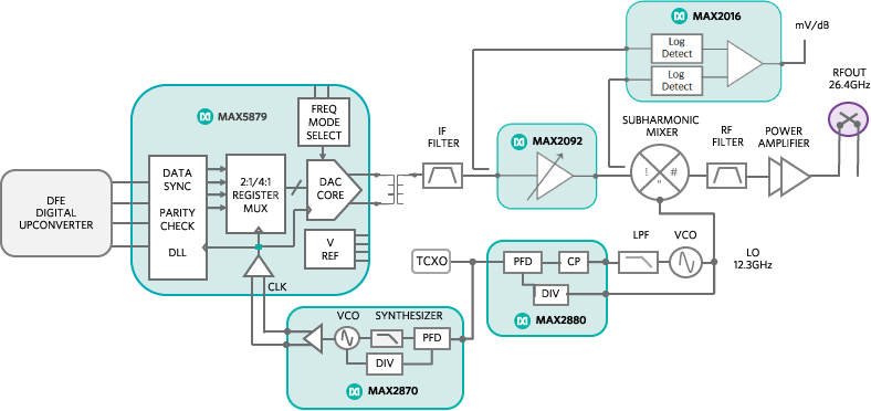
Figure 2. RF analog integration and high-performance building blocks are essential for microwave transmitter solutions.
The following sections provide an overview of the different backhaul solutions and market forces driving mobile backhaul deployments. They describe equipment and technology trends within the wireless backhaul segment and offer examples of how RF analog integration and RF building blocks support the point-to-point microwave and broadband satellite backhaul solution toolbox.
Different Types of Equipment for Mobile Backhaul
Wired and wireless backhaul solutions utilize broadband technologies that vary based on physical media and access method (Figure 3). Copper wire, hybrid fiber-coaxial (HFC) cable, and single-mode and multimode fiber-optic cable offer examples of wired backhaul physical media. Transport access technologies are fractional-T/E carrier (T1/E1), digital subscriber line (DSL), pseudowire, Ethernet, wave division multiplexing (WDM), and gigabit passive optical network (GPON). Availability of physical media, leasing cost, and data throughput requirements all influence the choice of wired backhaul.
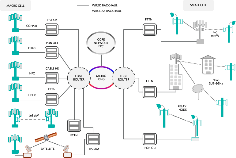
Figure 3. Mobile backhaul network physical media and access layer with macro-cell (left) and small-cell base station applications (right).
Wireless backhaul is needed when base stations do not have access to copper, HFC, or fiber transport. Wireless backhaul also makes sense when time to deployment is critical, or when leasing costs are prohibitive. Close to 70% of worldwide LTE base-station installations use wireless backhaul, according to industry estimates1. Line-of-sight (LOS) microwave, line-of-sight millimeter wave, non-line-of-sight (NLOS) sub-6GHz microwave, broadband satellite links, and inband or out-of-band relay nodes are among the methods for delivering wireless backhaul transport.
What's Driving Wireless Backhaul?
- The mobile wireless backhaul segment is driven by four primary factors:
- Exponential growth in mobile broadband traffic
- Rapid growth in mobile broadband subscriptions
- Increase in the number and type of base-station deployments (RAN density)
- Air-interface peak-data-rate evolution (Figure 4)
Mobile traffic is projected to grow at a compounded annual growth rate (CAGR) of 60%2 and broadband subscribers (LTE and HSPA) at a CAGR of 27%3 through 2018 (from 2013). In 2018 this translates to approximately 16 exabytes/month of mobile traffic and 6 billion broadband subscribers. Over the next four years the number of macro-cell base-station RF-transceiver shipments are anticipated to increase 51%4, and small-cell base-station shipment growth is forecast at over 43% CAGR5. Based on these projections, we expect to see significant RAN densification and network capacity gains. The evolution from 3G to LTE-A has seen theoretical peak downlink data rates increase 10x from 2010 to 2014 and is likely to extend beyond 3Gbps throughput when 5G is adopted in the future.
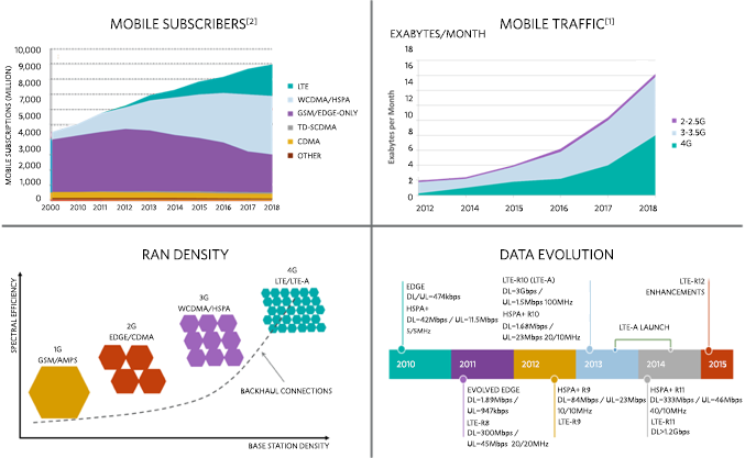
Figure 4. Segment trends driving the wireless backhaul market. Data sources for graphics are Cisco Virtual Networking Index Report 2 and Ericsson Mobility Report.3
As these four primary market drivers converge, we're seeing fast-growing demand for high-capacity wireless backhaul solutions. As mobile traffic, mobile subscribers, RAN density, and peak data rates all increase, then base-station capacity and wireless backhaul capacity must also increase.
Technology Drivers for Wireless Backhaul Equipment
Wireless backhaul equipment used in macro-cell and small-cell base-station applications all have some common technology drivers:
- Spectrally efficient, high-throughput radio links
- Low operating power
- Small form factor
- High reliability
The available RF spectrum is a finite and valuable resource that must be used efficiently, which makes spectrally efficient radio links essential. What’s more, licensing fees for more RF spectrum can burden the network operator’s total cost of ownership. High throughput is important because backhaul capacity, at a minimum, must match the base-station capacity in order to avoid compromising network performance. Low operating power is needed to minimize electrical energy usage, which yields lower operational expenditure (OPEX) and shrinks carbon emissions footprints. Low operating power also reduces heat dissipation, which enhances system reliability and allows smaller and lighter enclosures. A small-form-factor, zero-footprint solution is important because site and tower leasing costs are proportional to occupied space. So a smaller form factor reduces OPEX by lowering leasing cost. Finally, high reliability is critical to achieving service availability of “four nines” (i.e., 99.99%) or better and minimizing maintenance costs.
While the four technology innovation drivers are common to macro-cell and small-cell base-station applications, each base-station type and deployment scenario demands a unique and optimal wireless backhaul solution. That’s why a solution toolbox approach can best serve each wireless backhaul application.
A Peek Inside the Wireless Backhaul Toolbox
The HetNet comprises four general classes of base station: macro cell, metro cell, pico cell, and femto cell. Table 1 contrasts the types of base station, deployment scenarios, and the toolbox of possible wireless backhaul solutions. It shows that backhaul throughput for each base-station class must match the respective cell site capacity. An optimal wireless backhaul solution further aligns the throughput requirement with a particular deployment scenario. The method of wireless backhaul dictates radio band operation, radio design specification, and radio architecture.
Wireless backhaul radios operate over a wide spectrum of licensed and unlicensed RF bands extending to 80GHz (Figure 5). The RF spectrum for wireless backhaul ranges from sub-6GHz NLOS to C/Ka/Ku-band microwave LOS, and Q/V/E-band millimeter wave LOS. Each RF band has spectrum restrictions, channel bandwidth limitations, and propagation characteristics. Channel bandwidth can vary from 5MHz to 160MHz in NLOS systems; from 3.5MHz to 56MHz in microwave LOS systems; or from 28MHz to 112MHz and 250MHz to 5GHz in millimeter wave systems. Each of these specifications influences the type of modulation and carrier-to-noise ratio, which, in turn, dictates capacity trade-offs and link distance.
| BASE-STATION TYPE | DEPLOY SCENARIO | SUBSCRIBERS | CELL RADIUS (KM) | PA POPWER (dBm) | SIGNAL BW | SECTORS/ MIMO | BTS2 CAPACITY (THEORETICAL) | WIRELESS BACKHAUL SOLUTION |
| MACRO CELL | OUTDOOR | 200 TO 1000 | >1 | 50 | 100MHZ1 | 3 / 4X4 | 9GBPS3 | MICROWAVE, MILLIMETER, VSAT |
| METRO CELL | OUTDOOR | 200 | <1 | 38 | 40MHZ | 2 / 2X2 | 1.6GBPS | MICROWAVE, MILLIMETER, VSAT |
| PICO CELL | IN/OUTDOOR | 32 TO 100 | <0.03 | 24 | 20MHZ | 1 / 2x2 | 800MBPS | MILLIMETER, SUB-6GHZ, RELAY |
| FEMTO CELL | INDOOR | 4 TO 16 | <0.1 | 20 | 10MHZ | 1 / 2x2 | 400MBPS | SUB-6GHZ, RELAY |
|
1 ASSUMES CARRIER AGGREGATION AND POSSIBLE RAN SHARING.> 2 TOTAL BTS CAPACITY = CAPACITY PER SECTOR X NUMBER OF SECTORS 3 TAIL NODE CAPACITY PER SECTOR = DL+UL PEAK RATE, LTE-ADVANCED CATEGORY 5 WITH 15 BIT/SEC/HZ SPECTRAL EFFICIENCY |
||||||||
Modulation can entail simple QPSK used with wide-channel bandwidths or for operation in poor atmospheric conditions under low signal-to-noise-ratio (SNR) channel conditions. Conversely, high-order modulation up to QAM-2048 can be used with narrow bandwidths or for operation in high-SNR clear atmospheric conditions. The data throughput can range from 100Mbps to 10Gbps, based on link capacity requirements, installation scenario, SNR, and atmospheric conditions. Table 2 provides a summary of the different characteristics for each wireless backhaul method.
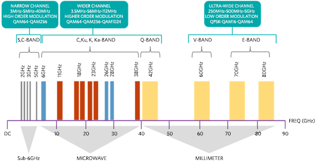
Figure 5. Wireless backhaul frequency spectrum, channel bandwidth, and modulation in licensed and unlicensed RF bands.
| EQUIPMENT TYPE | NLOS/LOS | PTP/PMP1 | BAND | LICENSE STATUS | CHANNEL BW ETSI, ANSI (MHZ) | MODULATION | ||
| MICROWAVE | LOS | PTP/PMP2 | C, KU, KA-BAND | LICENSE | 3.5/7/14/28/56 10/20/30/40/50 | QPSK TO 2048-QAM | ||
| MILLIMETER | LOS | PTP/PMP | Q-BAND | LICENSE | 28/56/112 | QPSK TO 2048-QAM | ||
| PTP | V-BAN | UNLICENSED | 250 (MIN) | QPSK TO 16-QAM, 64-QAM | ||||
| PTP | E-BAN | LIGHT LICENSE | 250MHZ - 5GHZ | |||||
| VSAT | LOS | PTP | C, KU, KA-BAND | LICENSED | 26/33/50/72/500 | QPSK, 8-PSK, 32-ASK |
||
| SUB-6GHZ | NLOS/LOS | PMP/PTP | S, C-BAND | LICENSE UNLICENSED | 5/10/20/40/80/160 | 64-QAM, 256-QAM OFDM | ||
| IN-BAND RELAY | NLOS | PTP | LTE BAND 1 - 43 | LICENSED | 5/10/15/20/40 | 64-QAM OFDM | ||
|
1 PTP = POINT TO POINT, PMP=POINT TO MULTIPOINT 2 PMP IN ASSIGNED BANDS |
||||||||
When selecting an optimal wireless backhaul solution, critical factors for the decision include system performance objectives and resource availability. System performance is predicated upon required capacity or data throughput, acceptable latency, expected quality-of-service, system scalability, and total cost of ownership (TCO). TCO comprises CAPEX and operational expense (OPEX) including energy cost, spectrum licensing fees, and site acquisition cost. Resource availability includes available RF spectrum, line-of-sight accessibility, site restrictions, prevailing atmospheric conditions, radio-link distance, and time to deployment. Table 3 summarizes some of these considerations.
| EQUIPMENT TYPE | NLOS LOS |
RANGE | LATENCY | CAPACITY SINGLE CHANNEL | APPLICATION | COMMENTS |
| MICROWAVE | LOS | <10km | <0.2ms | MID-HIGH 500Mbps | MACRO CELL SMALL CELL AGGREGATION |
HIGH RELIABILITY AND HIGH CAPACITY LINKS SUIT MACRO CELL APPLICATIONS |
| MILLIMETER | LOS | <4km (E-BAND) <<1km (V-BAND) |
<50us | MID-HIGH 300Mbps 10Gbps | SMALL CELL AGGREGATION MACRO CELL (E-BAND) |
V-BAND LEVERAGES NARROW BEAM AND OXYGEN ABSORPTION TO IMPROVE FREQUENCY REUSE |
| SATELLITE VSAT | LOS | >10km | <120ms (MEO) <330ms (GEO) |
MID-HIGH <1Gbps | SMALL CELL | REMOTE/RURAL SITES SERVE AREAS WITh NO INFRASTRACTURE MEO=MEDIUM EARTH ORBIT GEO=GEOSYNCHRONOUS EARTH ORBIT |
| SUB-6GHz | NLOS LOS |
1km (NLOS) 10km (LOS) |
<12ms | LOW-MID 500Mbpd | METRO, PICO, FEMTO | FAST DEPLOYMENT UNPREDICTABLE CAPACITY |
| IN-BAND RELAY | NLOS | <10km | +10ms | LOW-MID | PICO, FEMTO | OCCUPIES LTE SPECTRUM ADDS 10ms LATENCY TO DONOR ENODEB LATENCY |
A decision tree like that shown in Figure 6 can help guide the backhaul selection process6.
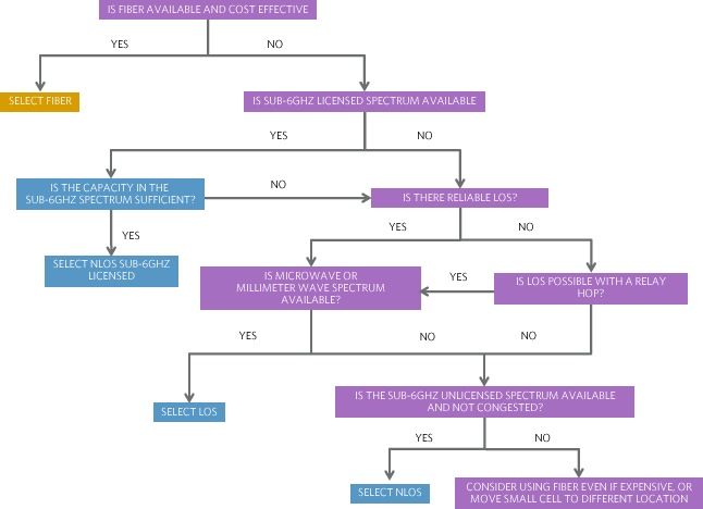
Figure 6. Backhaul decision tree. (Source: Senza Fili.6).
Trends in Equipment Configurations
Wireless backhaul equipment requires four key components: antenna, radio transceiver, modem, and interface. The antenna transmits and receives electromagnetic waves. The radio transceiver handles RF carrier frequency translation to and from the baseband. The modem modulates and demodulates the radio signals, and the interface moves information between the radio and TDM/IP transport. Differentiation among the four equipment types is distinguished by partitioning of the radio, modem, and interface. Figure 7 identifies the four different types of equipment configurations: all indoor unit (AIU), split mount unit (SMU), full outdoor unit (FODU, also called all outdoor unit, or AODU), and embedded.
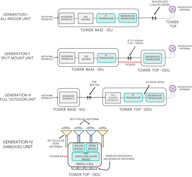
Figure 7. Wireless backhaul equipment configurations.
The evolution of Generation I through Generation IV equipment is characterized by a recognizable trend: more equipment is being moved up to the tower top, closer to the antenna. This trend seeks a zero-footprint design that eliminates indoor cooling cost, the need for indoor cabinet space, and RF signal loss.
For macro-cell base-station applications, the migration from indoor units to full outdoor units lowers power, improves signal quality, and lowers OPEX. Macro cells benefit from the FODU partition because RF loss in the waveguide or coaxial cable is minimized, or eliminated, which lowers RF power output and improves receiver input sensitivity. FODU reduces the indoor space needed for equipment housing; it does not require the special heating and cooling associated with indoor units. Together, these benefits yield lower operating cost and better system performance.
In small-cell base-station applications, the adoption of an embedded configuration means that systems can achieve a zero footprint with lower equipment cost. Small cells benefit from an embedded partition because a single unit houses the WAN, WLAN, and wireless backhaul radio functions. Now system size shrinks and installation is simplified. Also, RF losses associated with radio and antenna connections are significantly reduced because many small-cell deployments rely on E/V-band backhaul operating at 60GHz to 80GHz.
Figure 8 depicts a high-level block diagram of FODU with Power over Ethernet (PoE), employing advanced radio communication techniques that improve spectral efficiency and ensure link availability. The techniques include co-channel dual polarization (CCDP) and multiple input, multiple output (MIMO) spatial multiplexing with hot standby (HSB) redundancy. From the diagram, you can see how radio channel density is increasing. The diagram also highlights why RF analog integration is essential for achieving compact size. Part 2 of this application note series discusses system partitioning and relevant RF solutions.
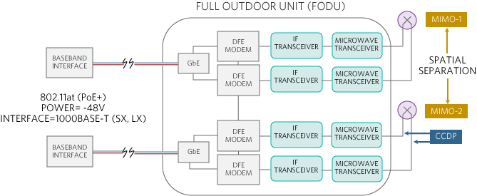
Figure 8. A PoE FODU with CCDP, 2x2 MIMO, and HSB.
Conclusion
This application note examines wireless backhaul applications, equipment trends, and the solution toolbox available for 4G and emerging 5G HetNet deployments. It presents different wireless technologies and radio bands used in microwave, millimeter wave, sub-6GHz, and satellite backhaul systems. It also explains how wireless backhaul equipment is evolving toward single integrated units featuring lower operating power, smaller size, and better radio performance. A caveat to achieving this feature set is the requisite for RF analog integration.
Part 2 of this application note series focuses on point-to-point microwave and broadband satellite systems typically used in macro-cell and small-cell base stations. The second part discusses techniques to improve radio-link spectral efficiency and radio lineup scenarios. Part 2 also explores the role of RF analog integration and RFIC building blocks and present relevant RF solutions.
この記事に関して
製品カテゴリ
{{modalTitle}}
{{modalDescription}}
{{dropdownTitle}}
- {{defaultSelectedText}} {{#each projectNames}}
- {{name}} {{/each}} {{#if newProjectText}}
-
 {{newProjectText}}
{{/if}}
{{newProjectText}}
{{/if}}
{{newProjectTitle}}
{{projectNameErrorText}}
最新メディア 2
