500mW PHS Transmitter Meets Transient Spectrum Requirements with Edge Control
要約
If the control signal's transition time is not controlled, the output spectrum of a 500mW PHS base station cannot meet the requirement. To use the MAX2510, only a simple circuit is added to insure a clean output spectrum during On/Off transients.
Introduction
The MAX2510 is a highly integrated IF transceiver for digital wireless applications. This is a ideal part to be used in PHS basestation application. Currently, the MAX2510 has been designed-in to a 20mW and 200mW PHS Base Station in China. However, when the MAX2510 is used in a 500mW output power PHS Base Station application, system characterization found that the spectrum re-growth does not meet the specification for spectral quality. This failure to meet spectral requirements was found to be due to high power output and a steep rising edge of the transmit-gate control signal.
This document presents the design trade-offs and simulation to reduce the spectral re-growth by adding slope control on the transmit-gate signal.
Design Target
The 500mW PHS basestation specification requires that the spurious emissions are 800nW, 250nW, 2.5mW at an offset from the center frequency of 600kHz, 900kHz and out-of-band respectively. The spurious energy is measured in a 30kHz bandwidth. There are three types of PHS basestation output-power ratings: 20mW, 200mW, and 500mW. These output power levels are measured in a bandwidth of 300kHz.
Table 1 lists the requirements for different output power PHS basestations.
| Offset Frequency | Output Power -> Spurious Emission | 20mW | 200mW | 500mW |
| 600kHz Offset | 800nW | 34dBc | 44dBc | 48dBc |
| 900kHz Offset | 250nW | 39dBc | 49dBc | 53dBc |
| Out of band | 2.5µW | 29dBc | 39dBc | 43dBc |
Design Approach and Simulation
In order to meet the above spectral re-growth requirement, we need to carefully design an analog slope-control circuit for the TX gate signal. The output power is controlled by a logic-level signal and the power ramp-up and ramp-down duration is limited to within 13µs.
We use a standard PHS source and a control signal with varying edge transition times and shapes.
Case #1: Linear edge shape, logic control signal is used to gate the PA on and off.
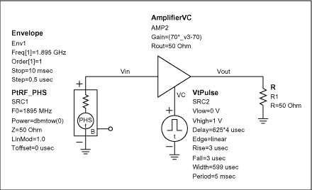
Figure 1.
The red colored spectrum is the standard (input) PHS spectrum and the blue trace is the PHS signal during a control-signal transition.
Based on this simulation, it is seen that the spectrum in the 600kHz and 900kHz offset is -45dBc and -48dBc, which cannot meet the requirement of a 500mW PHS base station. Therefore, we need to investigate a more complex slope-control circuit for the TX gate signal.
Case #2: TX gate control signal with cosine edge shape.
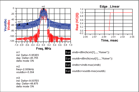
Figure 2.
Based these simulation results, we found that the spectrum at the 600kHz and 900kHz offset is -77dBc and -94dBc, which meets the PHS requirements. One can add a control circuit to generate a signal which produces an edge transition similar to a cosine.
Design Implementation
There are at least two methods to achieve the desired control signal effect:
1. Baseband Digital shaping:
We can create the desired cosine shape digitally. If one assumes that data is updated every microsecond, 13 data points would be needed to create this curve. Using an 8-bit DAC (digital to analog converter), and assuming a 1V range, the minimum voltage-step is about ~ 4mV.
A 13 x 8 look-up table in the baseband processor is created and stored in memory. Two methods are possible to create the desired transition look up table: One method is to simply compute the cosine values in the time domain. Another method is to observe the RF output spectrum and adjust the data until the spurious emissions requirement is met. The architecture of this control is shown in the figure below:
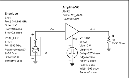
Figure 3.
2. Baseband Analog Shaping:
Baseband processors have great flexibility to create the desired control signal, but the digital approach requires modification of the baseband circuit and will occupy some baseband resources.
It is possible to achieve the desired result using a low pass filter to smooth the control signal which is sent from the baseband processor.
After design and optimization the circuit below was obtained:
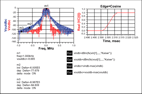
Figure 4.
According to this simulation, the spectrum at 600kHz and 900kHz offset is -83dBc and -92dBc, which meets the requirements.
When this circuit is added, the architecture appears as shown below:
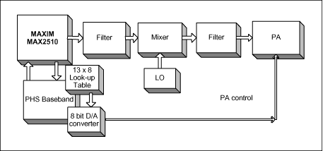
Figure 5.
According to the simulation, a 500mW PHS basestation will meet the requirements for spurious emissions with the addition of a simple edge shaping circuit on the PA enable control signal.
この記事に関して
製品
製品カテゴリ
{{modalTitle}}
{{modalDescription}}
{{dropdownTitle}}
- {{defaultSelectedText}} {{#each projectNames}}
- {{name}} {{/each}} {{#if newProjectText}}
-
{{newProjectText}}
{{/if}}
{{newProjectTitle}}
{{projectNameErrorText}}


