Programming and Debugging
The MAXREFDES178 uses the MAXDAP-Type-C DAPLink based debugger for debugging and programming. The OpenOCD tool gets installed among the development toolchain.
The MAXDAP-TYPE-C board has two Micro USB connectors. One Micro USB connector is directly connected to MAX32666 Microcontroller on the MAXREFDES178 Connectivity Board. This connector can be used for data transfer with the MAX32666 Microcontroller. The other Micro USB connector is present on the MAX32625PICO sub-board of MAXDAP-TYPE-C board. This connector is dedicated for debugging/programming operations. In Figure 9, the white Micro-USB cable is connected for debugging/programming and the black cable allows data transfer with MAX32666 Microcontroller.
Both cables can power the MAXREFDES178 and charge the battery. If there is no data transfer needed, connecting only the DAPLink Micro USB cable is sufficient.
 Figure 9. MAXREFDES178 and MAXDAP-Type-C connection.
The MAXDAP-TYPE-C board is a carrier board for the MAX32625PICO. It interfaces SWD interface to program/debug the MAX32666 Microcontroller and MAX78000 ICs using USB Type-C pins. The MAXREFDES178 uses several pins to physically carry SWD and UART signals. Figure 10 shows the interface diagram of MAXDAP-TYPE-C when connected to the MAXREFDES178 Connectivity Board.
 Figure 10. MAXDAP-TYPE-C interfaces.
If there is no programming and debugging needed, for data transfer or powering the MAX78000, a regular USB Type C cable can be used (Figure11).
 Figure 11. MAXREFDES178 with USB Type-C cable.
a. Programming and Debugging the MAX32666 Microcontroller
The MAX32666 Microcontroller on the Connectivity Board can be programmed through the MAXDAP-TYPE-C board. Connect MAXDAP-TYPE-C to MAXREFDES178 (Figure 12).
There are two Micro-USB connectors on the MAXDAP-TYPE-C board. One connector is for the on-board MAX32625PICO board for programming and debugging. The other Micro-USB connector connects the MAX32666 USB peripheral to a host.
For programming and debugging, the on-board MAX32625PICO board (embedded into the MAXDAP-TYPE-C board) must be connected.
 Figure 12. Programming the MAX32666 microcontroller on the connectivity board.
To start programming, the Maxim Integrated MSDK programming and debugging, on-board MAX32625PICO board (embedded into MAXDAP-TYPE-C board) must be connected.
b. Programming and Debugging MAX78000 ICs
The MAX78000 ICs on the MAXREFDES178 AI Board can also be programmed using the MAXDAP-TYPE-C board through the USB Type-C connector. To access the SWD interface of MAX78000 ICs instead of programming/debugging the MAX32666 microcontroller, plug the MAXDAP-TYPE-C board in reverse alignment Figure 13.
 Figure 13. MAXDAP-TYPE-C connection for MAX78000 ICs.
There are two MAX78000 ICs on the MAXREFDES178 AI Board and only one of them can be connected to MAXDAP-TYPE-C through the SWD interface at once. The MAX32666 can control the analog switches on the MAXREFDES178 AI Board using the SLAVE_DEBUG_SEL signal.
The MAX32666 can set the state of this signal by accessing the MAX7325 I2C IO expander. Table 5 describes the SLAVE_DEBUG_SEL signal to select and which MAX78000 IC to connect to the MAXDAP-TYPE-C board through the SWD interface.
Table 5. SLAVE_DEBUG_SEL Signal
| SLAVE_DEBUG_SEL STATE | Connection |
|---|
| 0 | MAX78000 Video is connected to SWD |
| 1 | MAX78000 Audio is connected to SWD |


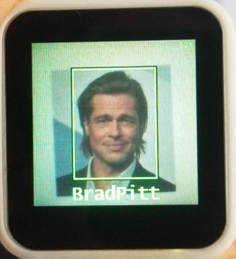
 Figure 1. MAXREFDES178 front view.
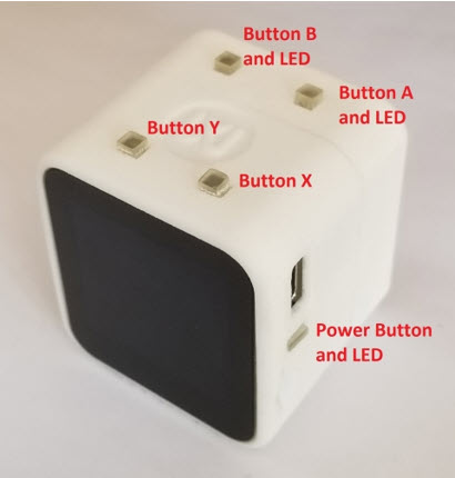
 Figure 2. MAXREFDES178 right side view.
 Figure 3. MAXREFDES178 left side view.
 Figure 4. MAXREFDES178 top view.
 Figure 5. Bottom view of the MAXREFDES178.
 Figure 6. MAXREFDES178 block diagram.
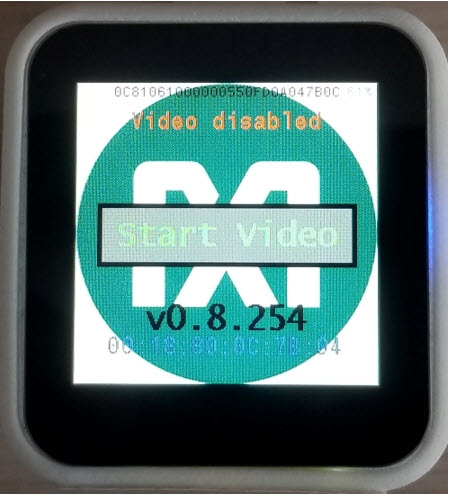
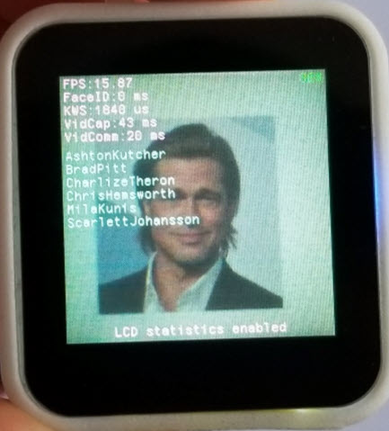
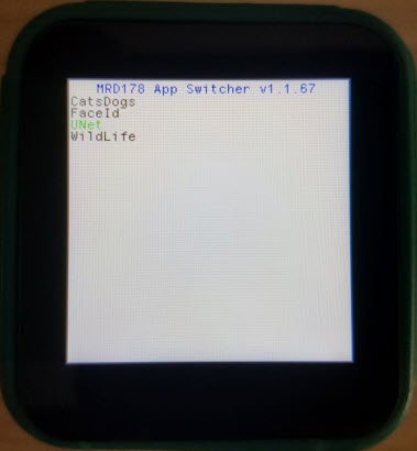 Selecting and loading a demo