MAXREFDES100


Overview
設計リソース
設計/統合ファイル
- Schematic
- Bill of Materials
- PCB Layout
- PCB CAD
- FAB Package
- PC GUI Program
- PC Serial Driver
- Android App
- App Source Code
- Default Binary Image
- Link to source codes
説明
マキシムのMAXREFDES100#ヘルスセンサープラットフォームは、お客様がマキシムの複雑で革新的な医療およびハイエンドフィットネスソリューションを評価するのに役立つ集積型センサープラットフォームです。このプラットフォームは、1つの生体電位アナログフロントエンドソリューション(MAX30003/MAX30004)、1つのパルス酸素濃度計および心拍数センサー(MAX30101)、2つの体温センサー(MAX30205)、1つの3軸加速度計、1つの3D加速度計と3Dジャイロスコープ、および1つの絶対気圧センサーを内蔵しています。
動作モード
ヘルスセンサープラットフォームは、下記の3つのモードのいずれかで使用可能です。
- テザーモード:ユーザーはUSB Type-A - Type-Cケーブルを使ってヘルスセンサープラットフォームをPCベースのGUIに接続することができます。このモードは、ECG、光、および温度センサーを含む、ボード上に実装された全センサーをサポートします。GUIは、クイックデモの実行(デフォルトのレジスタ設定を使用)、および個々のセンサーまたはアナログフロントエンドのレジスタ設定を変更することによって任意のセンサーを詳細に評価するオプションを提供します。
- 非テザーモード(オフライン):ヘルスセンサープラットフォームはデータを収集し、それを内蔵フラッシュに保存します。データは、ダウンロードして後処理することが可能です。このモードでは、センサーの設定および内蔵フラッシュへのミッションの書込みのために、テザーモードと同様にヘルスセンサープラットフォームをPC GUIに接続する必要がありますが、その後で切り離して非テザーモードで実行することができます。このモードで動作させるには、バッテリホルダーおよびコイン電池を実装する必要があります(ボックスには付属しません)。
- 非テザーモード(リアルタイム):お客様はリアルタイムでAndroidにデータをストリーミングすることができます(アプリはダウンロードいただけます)。プラットフォームをアプリに接続する方法を示すために、いくつかの機能を用意しました。お客様は、提供されているソースコードを、お客様の用途にあったアプリの開発に使用することができます。下記に、アプリ内で有効化されている機能のリストを示します。
- 温度センサーを使用する温度測定
- 圧力センサーを使用する気圧測定
- ECGアナログフロントエンドを使用する心拍数測定
- 加速度計を使用するボードの位置測定
「デザインリソース」タブには、PCおよびAndroidアプリケーションが提供されていて、すぐに、お使いいただけるようになっています。PCアプリケーションは、USB接続にて、全センサーの設定や対話形式での操作を可能にするグラフィカルユーザーインタフェース(GUI)を提供します。Androidアプリケーションは、BLE上でセンサーデータを監視する機能を提供します。アプリケーションのインストールおよび実行方法については、「詳細」タブをご覧ください。
プラットフォームの動作をカスタマイズしたいと考える開発者向けに、ARM mbed開発環境がサポートされています。プラットフォームとともに出荷されるコンパニオンプログラミングアダプタのMAXREFDES100HDK#により、ファームウェアアップデート用のドライバ不要なドラッグ&ドロッププログラミング、および仮想UARTインタフェースとCMSIS-DAP対応デバッガが提供されます。ファームウェア開発の詳細とソースコードの例については、ARM mbed開発者サイトのMAX32620HSPプラットフォームのページをご覧ください。
設計ファイル、ファームウェア、およびソフトウェアは、「デザインリソース」タブから入手可能です。また、ボードもご購入いただけます。
機能と利点
- 皮膚温
- 心拍数
- 生体電位測定(ECG)
- 動き
- 回転
- 気圧
Details Section
マキシムは、医療およびハイエンドフィットネスアプリケーション用の複雑で革新的なソリューションを築いています。これらのソリューションは、主としてマキシムの複数の製品ラインが根幹となっています。お客様がこれらのソリューションの特長を迅速に評価し、独自の設計を実現できるよう、マキシムは「hSensor」Platformと呼ばれる集積型センサープラットフォームを開発しました。このプラットフォームを使うと、お客様は様々な用途にマキシムの幅広い製品をより迅速かつ容易に評価することができます。また、hSensorプラットフォームは、マキシムのより新しいソリューションを設計やロードマップに取り入れることができる柔軟性も備えています。
hSensorプラットフォームは、動きの測定、高精度の皮膚温、および心電検査(ECG)、筋電検査(EMG)、脳波検査(EEG)を含む各種の生体電位測定に対応します。さらに、hSensorプラットフォームは、880nm (赤外線、IR)、660nm (赤色)、および537nm (緑色)の3つの波長でのパルス酸素濃度および心拍数(HR)検出を含む、各種の反射型フォトプレチスモグラフィー(光電式容積脈波)測定にも対応します。
このプラットフォームは、Windows®ベースのPCおよびAndroid®ベースの機器上で、簡素なデータ収集と視覚表示用のGUIアプリケーションをサポートします。設定およびデータ収集は、(USB Type-Cコネクタを介した) USB接続とBluetooth® low energy (BLE)無線の両方に対応します。
データ収集用に、フラッシュメモリ直接書込みモードがサポートされています。また、USB接続でのフラッシュメモリ読出しも実装されています。
このプラットフォームのマイクロコントローラには、システムの管理、プラットフォーム上の全デバイスのレジスタの制御、およびPCのGUIとの通信を行うファームウェアがプログラムされています。ユーザーがマイクロコントローラのファームウェアをカスタマイズする場合、詳細についてはmbedのファームウェア開発ガイドを参照してください(MAX32620HSPとして掲載されています)。
このリファレンスデザインのボックスには、以下のものが含まれています。
- MAXREFDES100#ボード:ヘルスセンサーボード
- MAXREFDES100HDK#ボード:MAXREFDES100#センサーボード用の開発ボード
- バッテリーホルダー:USBケーブルを使用しない場合にCR2032タイプのコイン電池を実装するため
- 2本のECGケーブル:ユーザーはこれらの2本のECGケーブルをボードにはんだ付けしてECG測定を行うことが可能
- USB Type-C ケーブル:PCとMAXREFDES100#ボード間の接続用
- Micro-USBケーブル:PCとMAXREFDES100HDK#ボード間の接続用
このプラットフォームを使って、以下の使用例を評価することができます。
- フィットネスアプリケーション
- 胸部ベースのアプリケーション
- HR内蔵チェストストラップ
- HRおよびECG内蔵チェストストラップ
- 手首ベースのアプリケーション
- 光学式HR内蔵スマートウォッチ
- 耳ベースのアプリケーション
- 光学式HR内蔵ヘッドフォン
- 胸部ベースのアプリケーション
- 医療アプリケーション
- 胸部ベースのアプリケーション
- 不整脈検出用1リードECGパッチ(ECGおよびHRのみ)
- 皮膚温測定
- 指ベースのアプリケーション
- 光学式SpO2測定
- 耳ベースのアプリケーション
- 光学式HRおよびSpO2
- 頭部ベースのアプリケーション
- 光学式HRおよびSpO2
- 腕ベースのアプリケーション
- ECG内蔵アームバンド
- 胸部ベースのアプリケーション
マキシムの全リファレンスデザインと同様、部品表(BOM)、回路図、レイアウトファイル、ガーバーファイル、ファームウェア、およびソフトウェアはすべてオンラインで入手可能です。
システムダイアグラム
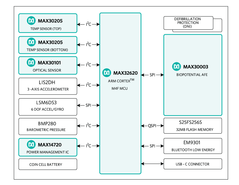
図1. MAXREFDES100#リファレンスデザインのブロック図
The MAX32620 microcontroller lies at the center of the hSensor platform. The following sensors are installed: MAX30003/MAX30004 biopotential analog front-end (AFE), MAX30205 human body temperature sensor, MAX30101 pulse oximeter and heart-rate sensor, LIS2DH 3-axis accelerometer, LSM6DS3 3D accelerometer and 3D gyroscope, and BMP280 absolute barometric pressure sensor.
Power Supplies
The hSensor platform can be powered by a USB connection or by a CR2032-type coin cell battery. When both USB and coin cell are attached the power is drawn from the USB due to MOSFET/Schottky diode at Q4. If a coin cell is attached without USB the coin cell is used to power the hSensor platform.
The hSensor platform uses a MAX14720 PMIC for the majority of the power management. The PMIC has internal programming such that a 3-second button press at SW1 turns the device on. A 20-second press at SW1 turns the PMIC off.
The PMIC has a power-on configuration that provides 1.2V, 1.8V and VSYS voltages. Here VSYS comes from SWOUT, which in turn comes from the battery or USB through the PMIC pin SWIN. After power-up, the microcontroller configures the PMIC for a boost voltage of 3.3V, which appears at the HVOUT pin.
While the PMIC provides the majority of power management there are some additional power supply chips. The temperature sensors are powered by a MAX8880 LDO, which is powered by HVOUT (3.3V) and regulates this down to 2.5V. The PMIC itself is fed by a MAX8881 3.3V LDO when the hSensor is attached to USB.
ESD protection is provided by the MAX3205, which attaches to all of the USB signals except for DP/DM, which have ESD protection provided by the MAX32620.
Mode selection signals
The hSensor platform uses the USB type C connector for debug (programming) and accessory signals. In some circumstances, these signals would contend with a USB host, so there is circuity to isolate these signals as needed.
The isolation is done with MAX4741 low-voltage analog switches. These switches are controlled by a combination of logic gates and MAX9064 single comparators.
The MAX9064 has an internal comparison voltage of 0.2V and two of them are used to monitor the USB pins A5 and B5 (typically designated as CC/VCONN). The USB A5 and B5 pins have 5.1kΩ pulldowns on the HSP board, a USB cable has a 56kΩ pullup on only pin A5 and a debug adapter board has 56kΩ pullups on both pin A5 and B5.
The following table indicates how the hSensor platform self-configures based on the USB A5 and B5 pins.
| USB Pin A5 | USB PIN B5 | Mode | Connection |
| Low | Low | Accessory | VIO and UART enabled by micro |
| Low | High | USB Cable |
All Accessory signals isolated |
| High | Low | ||
| High | High | Debug | SWD, RST, VIO, UART enabled |
MAX32620 Microcontroller
The MAX32620 is a 32-bit ARM® Cortex®-M4F (M4 plus floating point unit) microcontroller, suited for emerging medical and fitness applications. The architecture combines high-efficiency, signal-processing functionality with low cost, and ease of use. The device features 4 powerful and flexible power modes. Built-in dynamic clock gating and firmware controlled power gating minimize power consumption for any application. Multiple SPI, UART, and I2C serial interfaces, as well as a 1-Wire® master and USB, allow for interconnection to a wide variety of external sensors. A four-input, 10-bit ADC with selectable reference is provided.
Refer to the MAX32620 data sheet for details and design resources including evaluation kit, developing tools & user guides.
MAX30003/MAX30004 Biopotential AFE
The MAX30003/MAX30004 is a complete, biopotential AFE solution for wearable applications. It offers high performance for clinical and fitness applications, with ultra-low power for long battery life. The MAX30003/MAX30004 is a single biopotential channel providing ECG waveforms and heart-rate detection.
The biopotential channel has ESD protection, EMI filtering, internal lead biasing, DC leads-off detection, ultra-low power leads-on detection during standby mode, and extensive calibration voltages for built-in self-test. Soft power-up sequencing ensures no large transients are injected into the electrodes. The biopotential channel also has high-input impedance, low noise, high CMRR, programmable gain, various low-pass and high-pass filter options, and a high resolution analog-to-digital converter (ADC). The biopotential channel is DC coupled, can handle large electrode voltage offsets, and has a fast recovery mode to quickly recover from overdrive conditions, such as defibrillation and electrosurgery.
The MAX30003/MAX30004 interface is compatible with SPI/QSPI™/Micro-wire/DSP. In the hSensor platform, the MAX30003/MAX30004 communicates with the MAX32620 microcontroller through an SPI bus.
The MAX30003/MAX30004 is available in a 28-pin TQFN and 30-bump wafer-level package (WLP), operating over the 0°C to +70°C commercial temperature range.
For users who want to connect the ECG cables for measurement, remove R6, R21, R44, and R45 on the sensor board. Solder ECG cables on ECGP and ECGN pads on the sensor board.
Refer to the MAX30003/MAX30004 data sheet for details.
MAX30205 Human Body Temperature Sensor
The hSensor board has two MAX30205 installed, one on the top side and one on the bottom side.
The MAX30205 temperature sensor accurately measures temperature and provides an overtemperature alarm/interrupt/shutdown output. This device converts the temperature measurements to digital form using a high-resolution, sigma-delta ADC. The accuracy of the MAX30205 meets the clinical thermometry specification of the ASTM E1112 when soldered on the final PCB. Communication is through an I2C-compatible, 2-wire serial interface.
The I2C serial interface accepts standard write byte, read byte, send byte, and receive byte commands to read the temperature data and configure the behavior of the open-drain overtemperature shutdown output.
The MAX30205 features three address select lines with a total of 32 available addresses. The sensor has a 2.7V to 3.3V supply-voltage range, low-600µA supply current, and a lockup-protected I2C-compatible interface that make it ideal for wearable fitness and medical applications.
In the hSensor platform, the top side MAX30205 (U2) I2C address is 0b1001-001x, the bottom side MAX30205 (U12) I2C address is 0b1001-000x.
This device is available in an 8-pin TDFN package and operates over the 0°C to +50°C temperature range.
Refer to the MAX30205 data sheet for details.
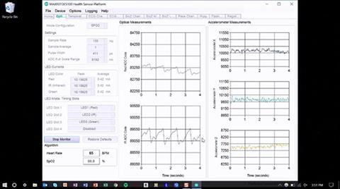
クイックスタートデモ:
GUIのHomeタブに3つのクイックスタートデモボタンがあり、それぞれのセンサーを設定して迅速にデモを実行することができます。
- ECG Demo:ECG ChannelおよびECG Muxタブのレジスタ設定を行い、Plotsタブに移動します。電極の接続後、Start MonitorをクリックしてECGのデモを行います。
- Optical Sensor Demo:Optical Sensorタブのレジスタ設定を行い、このタブに移動します。測定対象の位置に光センサーを配置した後、Start Monitorをクリックして光センサーのデモを行います。
- Temperature Sensor Demo:Temperature Sensorタブのレジスタ設定を行い、このタブに移動します。直ちに温度の表示が開始されます。ボードの各面に1つずつ、2つの温度センサーがあります。
Androidアプリケーションのクイックスタートガイド
hSensor Androidアプリは、Android機器上で動作するGUIプログラムです。このプログラムはhSensorのデータを収集し、機器の画面上にグラフィック表示します。このプログラムは、Bluetooth 4.0 Low Energy無線を介してhSensorハードウェアと通信します。
必要機器:
- MAXREFDES100#ボード
- 少なくともバージョン4.4が動作するAndroid機器
- Bluetooth 4.0対応のAndroid機器
- 1つのCR2032コイン電池(オプション)
- 空きUSBポートのあるPC (バッテリー給電の場合はオプション)
- 1本のUSB Type-A - Type-C ケーブル(バッテリー給電の場合はオプション)
- CR2032コイン電池をバッテリーホルダーB1に装着します。
- バッテリーがない場合、USB Type-A - Type-C ケーブルでhSensorプラットフォームハードウェアをPCまたはMacに接続します。
- ボード上のSW1スイッチを押して離します。スイッチの横にある赤いLEDが点滅します。
- MAXREFDES100#のウェブページにある最新の MAXREFDES100# AndroidアプリMAXREFDES100_Androidxxx.zipをダウンロードします。それを解凍して機器にインストールします。このアプリには、Android 4.4 以降が必要です。
- MAXREFDES100アイコンをタップして、hSensor Androidアプリを起動します。
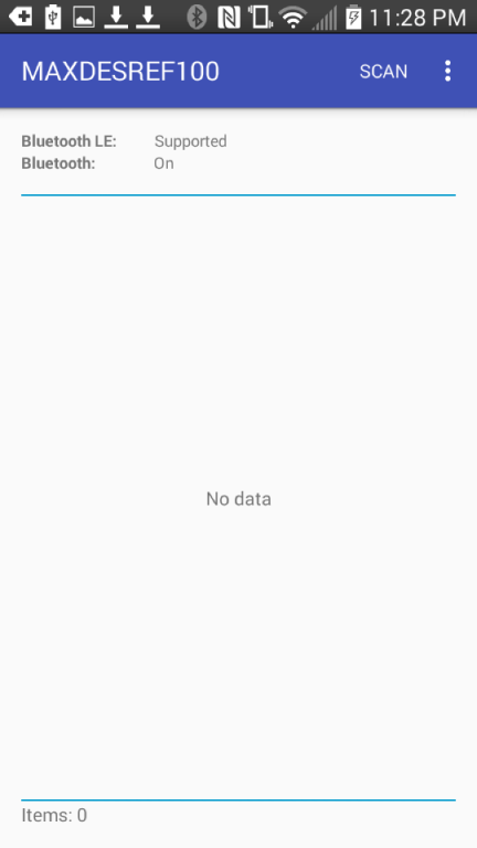
図16. Androidアプリケーションのスクリーンショット1
- 画面下部にあるScanボタンをタップします。スキャンによって、現在Bluetooth 4.0を使ってアドバタイズを行っている全デバイスが表示されます。
- リスト内のMAXREFDES100デバイスをタップして、hSensorプラットフォームハードウェアに接続します。
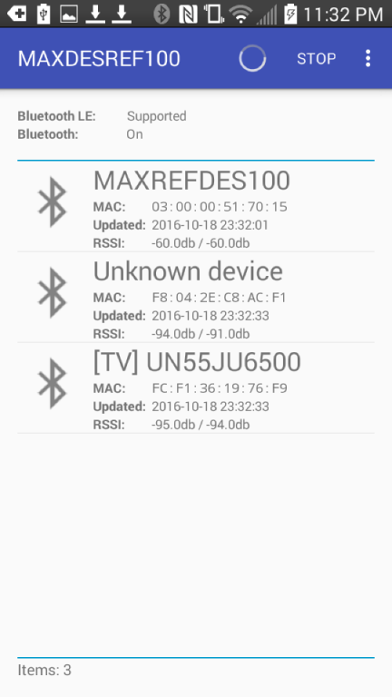
図17. Androidアプリケーションのスクリーンショット2
- 下図の画面が表示されます。
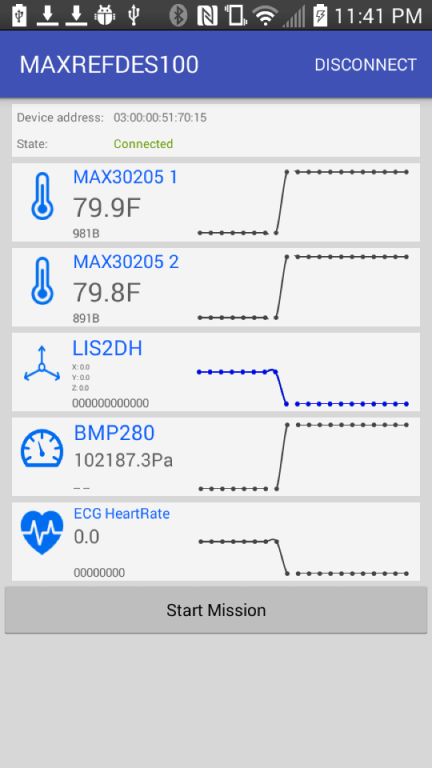
図18. Androidアプリケーションのスクリーンショット8
Documentation & Resources
-
MAXREFDES100 Design Files2021/02/16ZIP35 M
Support & Training
Search our knowledge base for answers to your technical questions. Our dedicated team of Applications Engineers are also available to answer your technical questions.