Using the MAXQ2000 to Implement a High-Speed I²C Interface for the MAX1169
要約
This note shows an application circuit and provides all the firmware required to interface the MAXQ2000 microcontroller (MAXQ20 core) to the MAX1169 16-bit ADC. The example firmware was developed using the Rowley CrossWorks IDE Version 1.0.
MAX1169 Overview
The MAX1169 is a 16-bit, low-power ADC featuring a 1.7MHz high-speed I2C-compatible serial interface. The MAX1169 supports both Fast Mode (400kHz) and High-Speed Mode (up to 1.7MHz).
Hardware Overview
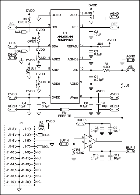
The application circuit utilizes the MAX1169 evaluation (EV) kit and MAXQ2000 EV kit. The MAX1169 EV kit consists of the MAX1169, all required passive components, and a proven PCB layout. A schematic of the kit is shown in Figure 1. The MAXQ2000 microcontroller is not present on the MAX1169 EV kit board; it was, however, added to the system by connecting SCL, SDA, and GND from the MAXQ2000 EV kit to the MAX1169 EV kit. In addition, apply +3.3V to DVDD and +5V to AVDD, respectively.

Figure 1. MAX1169 EV kit schematic.
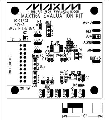
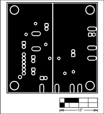
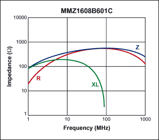
The pinout of the MAX1169 allows easy isolation of the analog section from the digital section. The analog section is grouped together on pins 8 through 13 on the right side of the IC, and the digital section is located on pins 1 through 7 on the left side of the IC. Pin 14 is also part of the digital section, but can be easily grouped with the left side of the IC. An example component placement is shown in Figure 2. For optimum performance it is recommended that designers use separate analog and digital grounds, as shown in Figure 3. Connect both ground planes near the MAX1169 through a ferrite bead. Using a ferrite bead such as the TDK MMZ1608B601C to connect both grounds prevents the microcontroller's system clock and its harmonics from feeding into the analog ground. Knowing that the system clock of the MAXQ2000 is 20MHz, the MMZ1608B601C was chosen for its specific impedance versus frequency characteristics. Figure 4 shows the impedance versus frequency curve for the MMZ1608B601C.

Figure 2. MAX1169 EV kit component placement.

Figure 3. The MAX1169 EV kit implements separate analog and digital grounds.

Figure 4. The MMZ1608B601C ferrite bead impedance versus frequency characteristics.
The MAXQ2000 EV kit contains a complete set of software, hardware, sample code, and documentation needed to start designing with MAXQ2000 microcontroller. Schematics for the MAXQ2000EV kit are available in the kit's data sheet.
Firmware Overview
The example firmware was developed using the Rowley CrossWorks IDE Version 1.0. Information on Rowley CrossWorks and other third-party development tools for the MAXQ® microcontrollers is available on the Maxim website.
The CrossWorks main source file (main.c) initializes the MAXQ2000's UART, calls the high-speed I2C read function from hsi2c.asm, and transmits the MAX1169's sampled data over the serial port. Any serial port application such as TeraTerm can be used to view the samples on the PC.
The hsi2c.asm file was written in assembly and is the high-speed I2C firmware driver. The example assembly program collects samples from the MAX1169 by bit-banging a high-speed I2C interface on the MAXQ2000's general-purpose input/output (GPIO) ports. The MAXQ2000's 20MHz system clock allows the bit-banged high-speed I2C interface to run up to 1.7MHz.
The hsi2c.asm file must be customized before the driver can be used.
- Edit the I2C_ADDR define statements to reflect the I2C address of your part. For example, a 0x7F address is encoded as:
  I2C_ADDR7  equ 0
  I2C_ADDR6  equ 1
  I2C_ADDR5  equ 1
  I2C_ADDR4  equ 1
  I2C_ADDR3  equ 1
  I2C_ADDR2  equ 1
  I2C_ADDR1  equ 1
- The source expects a 20MHz system clock (MAXQ2000 Crystal).
Download: Source Code (ZIP, 10.5kB)
Conclusion
The specification for high-speed I2C has existed since January 2000. Yet few, if any, microcontrollers are available today with an internal high-speed I2C peripheral. This is unfortunate since several devices, such as ADCs, DACs, CODECs, and even power supplies, are being designed to support the high-speed I2C interface. This application note provides a much-needed, working high-speed I2C example.