NRZ Applications
要約
This application note covers how to decouple a framer from the line interface unit (LIU) so that the user can connect the LIU/framer to a Bipolar or NRZ mode device.
This application note applies to following single-chip transceivers: (T1) DS21352, DS21552, DS21Q352, and DS21Q552; (E1) DS21354, DS21554, DS21Q354, and DS21Q554; and (combination) DS2155, DS2156, DS21Q55, and DS21Q56.
Overview
The line interface unit (LIU) can be completely decoupled from the framer/formatter to interface to optical, HDSL, or other devices with an NRZ interface. It can then be used to corrupt data, insert framing errors, or insert CRC errors, etc.
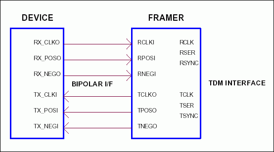
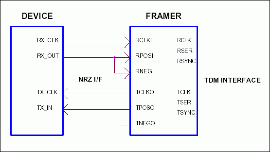
The framer/formatter can generate/detect either bipolar or NRZ data format (determined by the ODF bit). Table 1 shows the register settings for the output data format. Figures 1 and 2 show how to interface the framer/formatter to devices with bipolar or NRZ data modes.
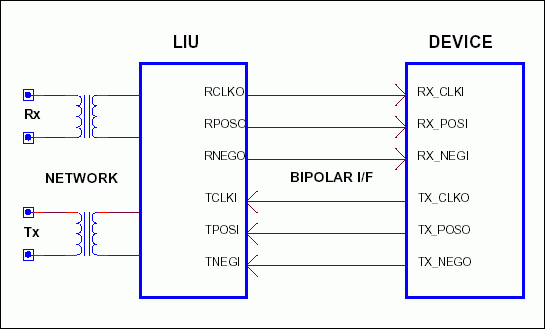
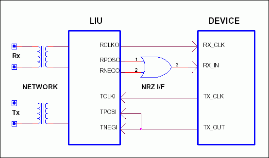
When the LIU receive side is interfaced to a device with NRZ data format, an OR-gate must be added to convert the bipolar data format into NRZ. See Figures 3 and 4 for both data mode applications.
Table 1. Output data format (ODF) regsiter settings
| TESE | ODF | RSAO | TSCLKM | RSCLKM | RESE | PLB | FLB | FUNCTION |
| X | 0 | X | X | X | X | X | X | Bipolar data |
| X | 1 | X | X | X | X | X | X | NRZ data |
| ODF | TFPT | T16S | TUA1 | TSiS | TSA1 | TSM | TSIO | FUNCTION |
| 0 | X | X | X | X | X | X | X | Bipolar data |
| 1 | X | X | X | X | X | X | X | NRZ data |
| RSMS | RSMS2 | RSMS1 | RSIO | TSDW | TSM | TSIO | ODF | FUNCTION |
| X | X | X | X | X | X | X | 0 | Bipolar data |
| X | X | X | X | X | X | X | 1 | NRZ data |
The DS2155/56 provides a software control bit to separate or connect the LIU/framer when the LIUC pin is hardwired high. If the LIUC pin is connected low, then the LIUC bit has no effect (Table 2).
| -- | -- | -- | LIUC | LLB | RLB | PLB | FLB | FUNCTION |
| X | X | X | 0 | X | X | X | 0 | LIUC control |
| LIUC PIN | LIUC BIT | FUNCTION |
| 0 | 0 | LIU and framer separated |
| 0 | 1 | LIU and framer separated |
| 1 | 0 | LIU and framer connected |
| 1 | 1 | LIU and framer separated |

Figure 1. Framer connection to bipolar mode device.

Figure 2. Framer connection to NRZ mode device.

Figure 3. LIU connection to bipolar device.

Figure 4. LIU connection to NRZ mode device.