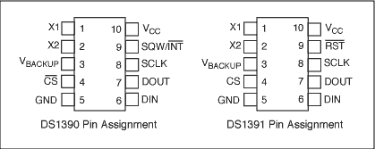
SPIを用いてDS1390/DS1391 RTCをMotorola DSPに接続
要約
このアプリケーションノートでは、SPI™インタフェースモジュールを内蔵したMotorola DSPにDS1390を接続する方法について説明します。この回路ではMotorola DSP56F800DEMOデモボードおよびCodeWarrior®のIDEを使用します。
概要
DS1390リアルタイムクロック(RTC)は、SPIインタフェースを使用してマイクロコントローラ(µC)または Digital Signal Processing (DSP)ユニットに接続することができます。このアプリケーションノートでは、SPIインタフェースモジュールを内蔵したMotorola DSPにDS1390を接続する方法について説明します。この回路では、Motorola DSP56F800DEMOデモボードとCodeWarriorのIDEを使用します。
サンプルソフトウェアの使用
サンプルソフトウェアは、ブランクプロジェクトを出発点として開発したものです。詳細については、「Motorola Kit Installation Guide (Tutorial: Creating a CodeWarrior Project)」の指示に従ってください。このアプリケーションノートに含まれているコードをmain.cに追加してください。
動作
このプログラムは、GPIOポートを使用して、DS1390のCS信号を制御しています。ソフトウェアは、SPIコントローラモジュールを初期化し、DSPが時刻と日付をDS1390に書き込みます。次に、ソフトウェアは、時刻と日付の読み取りを繰り返します。DS1390とDS1391は、SPIモードの1と3に対応しています。
回路図を図1に示します。この回路は、ドーターカードとして構成され、Motorolaのデモボードに取り付けられます。図1の回路には、SPIインタフェースを備えた複数のRTCが搭載されています。一度に使用できるRTCは1つだけで、ソフトウェアはDS1390のみをサポートしています。ソフトウェアを図2に示します。

図1.

拡大画像 (PDF, 138kB)
図2. ドーターカードの回路図
図3. コードのリスト出力
/* File: DS1390.c */
/* This example program was developed using the Motorola
56F800 Demo Board Kit.  Follow the kit instalation guide
for creating a CodeWarrior Project.  Use the shell of the
new project for this example.  Note: This program is for
example only and is not supported by Dallas Semiconductor
Maxim. */

#include "port.h"
#include "stdio.h"
#include "stdlib.h"

/*******************************************************
* Main program for use with Embedded SDK
*******************************************************/

extern sampleASM (void);

void reset_spi(void);
void wbyte_spi(unsigned char);
void init_sci0(Word16);
tx_sci0(unsigned char);
void bcd2ascii(unsigned char);
unsigned char  rbyte_spi(void);

#define	REG_BASE 0x0000
#define	SCI0_BASE 0x0F00
#define	SPI_BASE 0x0F20
#define	GPIOA_BASE 0x0FB0
#define	GPIOB_BASE 0x0FC0

#define	SCI0_SCIBR *(volatile UWord16 *)(SCI0_BASE + 0)
#define	SCI0_SCICR *(volatile UWord16 *)(SCI0_BASE + 1)
#define	SCI0_SCISR *(volatile UWord16 *)(SCI0_BASE + 2)
#define	SCI0_SCIDR *(volatile UWord16 *)(SCI0_BASE + 3)

#define	SPSCR *(volatile UWord16 *)(SPI_BASE + 0)
#define	SPDSR *(volatile UWord16 *)(SPI_BASE + 1)
#define	SPDRR *(volatile UWord16 *)(SPI_BASE + 2)
#define	SPDTR *(volatile UWord16 *)(SPI_BASE + 3)

#define	GPIO_A_PUR *(volatile UWord16 *)(GPIOA_BASE + 0)
#define	GPIO_A_DR *(volatile UWord16 *)(GPIOA_BASE + 1)
#define	GPIO_A_DDR *(volatile UWord16 *)(GPIOA_BASE + 2)
#define	GPIO_A_PER *(volatile UWord16 *)(GPIOA_BASE + 3)

#define	GPIO_B_PUR *(volatile UWord16 *)(GPIOB_BASE + 0)
#define	GPIO_B_DR *(volatile UWord16 *)(GPIOB_BASE + 1)
#define	GPIO_B_DDR *(volatile UWord16 *)(GPIOB_BASE + 2)
#define	GPIO_B_PER *(volatile UWord16 *)(GPIOB_BASE + 3)

void main (void)
{
unsigned char	msec=0, min=0x26, sec=0x00, hr=0x17, dow=0x06,
				date=0x26, mon=0x12, yr=0x03, write = 0;

	reset_spi();
	init_sci0(195);			// 30MHz / 195 = 9600 baud

	GPIO_B_DR = 0x0008;		// disable RTC - CS high

	GPIO_B_DR = 0;			// enable RTC - CS low
	wbyte_spi(0x8d);		// control register write address
	rbyte_spi();			// dummy read
	wbyte_spi(0x18);		// enable osc, 32kHz sqw
	rbyte_spi();
	GPIO_B_DR = 0x0008;		// disable RTC - CS high

	if(write)
	{
		GPIO_B_DR = 0;			// enable RTC - CS low
		wbyte_spi(0x80);		// select seconds register write address
		rbyte_spi();			// dummy read
		wbyte_spi(msec);		// milliseconds register data
		rbyte_spi();
		wbyte_spi(sec);			// seconds register data
		rbyte_spi();
		wbyte_spi(min);			// minutes register
		rbyte_spi();
		wbyte_spi(hr);			// hours register
		rbyte_spi();
		wbyte_spi(dow);			// day of week register
		rbyte_spi();
		wbyte_spi(date);		// date register
		rbyte_spi();
		wbyte_spi(mon);			// month register
		rbyte_spi();
		wbyte_spi(yr);			// year register
		rbyte_spi();
		GPIO_B_DR = 0x0008;		// disable RTC - CS high
	}
	while(1)
	{
		GPIO_B_DR = 0u;			// enable RTC - CS low

		wbyte_spi(0);			// seconds register read address
		rbyte_spi();			// dummy read
		wbyte_spi(0);
		msec = rbyte_spi();		// read milliseconds register
		wbyte_spi(0);
		sec = rbyte_spi();		// read seconds register
		wbyte_spi(0);
		min = rbyte_spi();		// ditto minutes
		wbyte_spi(0);
		hr = rbyte_spi();		// and so on
		wbyte_spi(0);
		dow = rbyte_spi();
		wbyte_spi(0);
		date = rbyte_spi();
		wbyte_spi(0);
		mon = rbyte_spi();
		wbyte_spi(0);
		yr = rbyte_spi();

		GPIO_B_DR = 0x0008;		// disable RTC - CS high

		tx_sci0(0x0d);			// sequence to print time & date
		tx_sci0(0x0a);
		bcd2ascii(yr);
		tx_sci0('/');
		bcd2ascii(mon);
		tx_sci0('/');
		bcd2ascii(date);
		tx_sci0(' ');
		bcd2ascii(hr);
		tx_sci0(':');
		bcd2ascii(min);
		tx_sci0(':');
		bcd2ascii(sec);
	}

	return;
}

//SPSCR
//15 14  13   12     11   10    9     8    7       6       5    4        3    2    1    0
// r MSB SPRF ERRIE  ovrf modf spte modfen spr1   spr0   sprie spmstr   cpol cpha spe  spite

void reset_spi()
{
int	val;
	SPSCR = 0x0056;	// SPR0, SPMSTR, CPHA, SPE
	SPDSR = 0x0007;	// 8-bit size

	SPSCR &= 0xfffd;	// clear spe, resets SPI (partial)
	SPSCR |= 0x0002;	// set spe, new values take effect

	GPIO_B_PER = 0x00f3;	// use GPIOB3 as CS for RTC
	GPIO_B_DDR = 0x000d;	// direction is output

	GPIO_A_PER = 0x00f9;	// enable/disable per function (1=enable)
	GPIO_A_DDR = 0x0006;	// direction is output (1=output)
	GPIO_A_DR  = 0;			// write bits low (0=low)
}

void  wbyte_spi( unsigned char  wbyte)	// ------ write one byte -------
{
	while (!(SPSCR & 0x0200));	// wait for transmitter empty flag

	SPDTR = wbyte;
}

void	bcd2ascii(unsigned char dat)	// ----- convert bcd to ascii and send to sci ----
{
	tx_sci0( (dat >> 4) + 0x30);
	tx_sci0( (dat & 0x0f) + 0x30);
}
unsigned char rbyte_spi(void)	// -------- read one byte ----------
{
	while (!(SPSCR & 0x2000));	// wait for receiver full flag

	return(SPDRR);

}

void	init_sci0(Word16 baud)
{
	GPIO_B_PER = 0x00f3;	// set up
	GPIO_B_DDR = 0x000d;	// direction is output

	SCI0_SCIBR = baud;		// baud rate
	SCI0_SCICR = 0x2000;	// control reg
}
tx_sci0(unsigned char val)
{
UWord16	reg;

	SCI0_SCICR &= 0xfffb;	// turn receiver off
	SCI0_SCICR |= 8;		// turn transmitter on
	do
	{
		reg = SCI0_SCISR;		// clear flag by reading
	}	while( (reg & 0x8000) == 0);	// wait until RDRF is false

	SCI0_SCIDR = (unsigned int) (val);
}