Design Note 379: Easy Drive ADCs Simplify Measurement of High Impedance Sensors
Delta-sigma ADCs, with their high accuracy and high noise immunity, are ideal for directly measuring many types of sensors. Nevertheless, input sampling currents can overwhelm high source impedances or low-bandwidth, micropower signal conditioning circuits. The LTC2484 family of delta sigma converters solves this problem by balancing the input currents, thus simplifying or eliminating the need for signal conditioning circuits.
A common application for a delta-sigma ADC is thermistor measurement. Figure 1 shows the LTC2484 connections for direct measurement of thermistors up to 100kΩ. Data I/O is through a standard SPI interface and the sampling current in each input is approximately:

or about 1.67μA when VREF is 5V and both inputs are grounded.
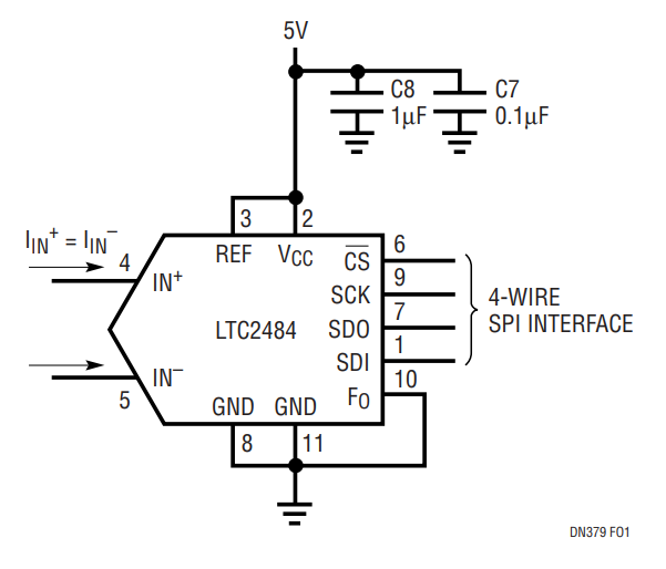
Figure 1. LTC2484 Connections.
Figure 2 shows how to balance the thermistor such that the ADC input current is minimized. If reference resistors R1 and R4 are exactly equal, the input current is zero and no errors result. If the reference resistors have a 1% tolerance, the maximum error in the measured resistance is 1.6Ω due to the slight shift in common mode voltage; far less than the 1% error of the reference resistors themselves. No amplifier is required, making this an ideal solution in micropower applications.
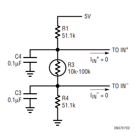
Figure 2. Centered Sensor.
It may be necessary to ground one side of the sensor to reduce noise pickup or simplify wiring if the sensor is remote. The varying common mode voltage produces a 3.5kΩ full-scale error in the measured resistance if this circuit is used without buffering.
Figure 3 shows how to interface a very low power, low bandwidth op amp to the LTC2484. The LT1494 has excellent DC specs for an amplifier with 1.5µA supply current—the maximum offset voltage is 150µV and the open loop gain is 100,000—but its 2kHz bandwidth makes it unsuitable for driving conventional delta-sigma ADCs. Adding a 1kΩ, 0.1µF filter solves this problem by providing a charge reservoir that supplies the LTC2484’s instantaneous sampling current, while the 1kΩ resistor isolates the capacitive load from the LT1494. Don’t try this with an ordinary delta-sigma ADC—the sampling current from ADCs with specifications similar to the LTC2484 family would result in a 1.4mV offset and a 0.69mV full-scale error in the circuit shown in Figure 3. The LTC2484’s balanced input current allows these errors to be easily cancelled by placing an identical filter at IN–.

Figure 3. Grounded, Buffered Sensor.
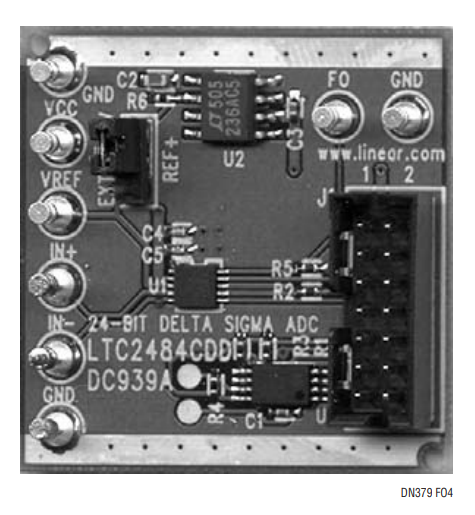
Figure 4. LTC2484 Demo Board.
Figure 5. LTC2484 Demo Software Screenshot Showing Microvolt Offset and 600nVRMS Noise
著者
