Bipolar Stepper-Motor Driver has Few Components
要約
As an alternative to the otherwise complex driver circuit for a stepper motor, this approach employs a tiny, surface-mount 2.8W class D audio amplifier that normally drives 4W or 8W speakers. Two internal H-bridges drive the output pairs OUTR± and OUTL±, which connect directly to the A and B windings of the stepper motor. Each pair carries a differential PWM signal with a nominal center frequency of 1.22MHz.
Introduction
This design idea appeared in the December 1, 2006 issue of EDN magazine.
Bipolar, monofilar-winding stepper motors provide strong torque for a given size, but they are expensive and they require eight driving transistors: four in an H-Bridge configuration for each of the two motor windings. Because each transistor must be able to withstand and quickly recover from over-current and short-circuit conditions, a typical motor-driver circuit is complex and physically large.
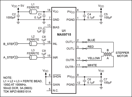
As an alternative for such motors, consider the tiny, surface-mount driver circuit of Figure 1. The low-EMI, filterless, 2.8W class D audio amplifier (MAX9715, U1) is typically used to drive 4Ω or 8Ω speakers. Two internal H-bridges drive the output pairs OUTR± and OUTL±, which connect directly to the A and B windings of the stepper motor. Each pair carries a differential PWM signal with nominal center frequency of 1.22MHz.

Figure 1. This small surface-mount circuit drives a bipolar monofilar-winding stepper motor.
Capacitors C1, C3, C4, and C6 provide bypassing for the associated U1 pins, C8–C9 limit the input bandwidth to 16Hz, and L2-L3 block any electrical noise picked up by the long input cables. The VDD input is filtered by a pi noise filter consisting of C1, C2, and the ferrite bead L1. C5 and C7 provide bulk-holdup capacitance for the class D power-amplifier outputs.
A suitable controller feeds digital pulses to the A_Step and B_Step inputs, which represent the motor's right and left channels respectively. Internal short-circuit and thermal protection guards the amplifier against overcurrent and short circuits caused by the stepper motor or its connecting leads.
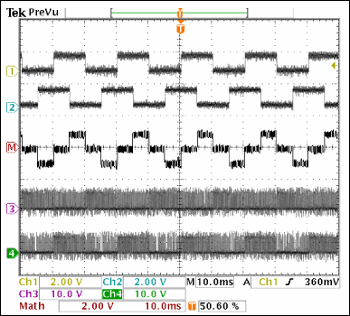
Table 1 illustrates the sequence of A_Step and B_Step pulses required to drive a typical stepper motor in the forward direction (Figure 2). (Simply apply steps 0 through 4, continually.) To reverse the motor, you reverse the pattern by beginning at the bottom of the table and working upwards. Again, C8 and C9 limit the minimum pulse rate to 16Hz. If desired, you can disable the amplifier by applying a logic low to the active-low SHDN input (pin 8).

Figure 2. Waveforms from the Figure 1 circuit: A_Step input (Ch 1), B_Step input (Ch 2), OUTR+ (Ch 3), OUTR- (Ch 4), and the signal actually seen by the motor windings (OUTR+ minus OUTR-), which is computed by the scope as "Math."
| Step # | A_Step | B_Step |
| 0 | H | L |
| 1 | L | L |
| 2 | L | H |
| 3 | H | H |
| 4 | H | L |