資料ライブラリ
AN-2584: Interfacing an AD7124-8 with MAX32625 Based on Cortex M4
Introduction
This application note describes how to connect evaluation boards and how to easily develop AD7124-8 sigma-delta (Σ-Δ) ADC using the Cortex-M4® based precision Analog Devices Inc., microcontrollers, such as the MAX32625. The MAX32625 is an ultra-low power microcontroller unit (MCU) from Analog Devices that can operate up to 96 MHz, with integrated 512 kB flash and 160 kB SRAM. It can support universal asynchronous receiver-transmitter (UART), SPI, I2C, USB, and up to 40 GPIOs. All GPIO pins can be configured to 1.8 V or 3.6 V by software. Its built in high secure features and encryption algorithm helps users to safe guard their firmware.
This application note also includes example code showing how a microcontroller and Σ-Δ ADC can communicate with each other via the SPI interface. This example code is based on resistance temperature detector (RTD) applications.
Interfacing the Evaluation Boards
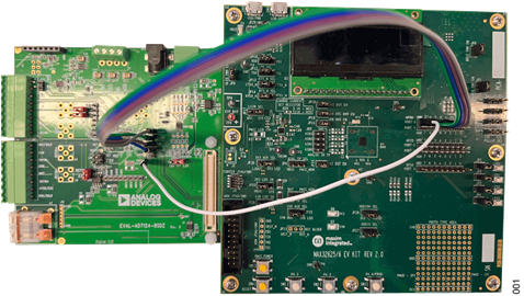
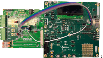
Analog Devices offers evaluation boards that allow quick prototyping of an application. For example, consider the MAX32625 (MAX32625-EVKIT) and the AD7124-8 (EVAL-AD7124-8) evaluation boards. Figure 1 shows MAX32625-EVKIT connected to EVAL-AD7124-8.
| Test Pin | Signal | Description |
| TSCLK | SCLK | Serial Clock Input. The serial clock input is for data transfers to and from the AD7124-8. |
| CS | CS | Chip Select Input. This is an active low logic input that selects the AD7124-8. The device is disabled when this pin is high. |
| TDIN | DIN | Serial Data Input to the Input Shift Register on the AD7124-8. Data in the input shift register is transferred to the control registers within the ADC, with the register selection bits of the communications register identifying the appropriate register. |
| DOUT | DOUT/RDY | Serial Data Output/Data Ready Output. DOUT/RDY functions as a serial data output pin to access the output shift register of the ADC. In addition, DOUT/RDY operates as a data ready pin, going low to indicate the completion of a conversion. |
| GND5 | GND | Analog and Digital Ground. |
AD7124-8 Evaluation Board
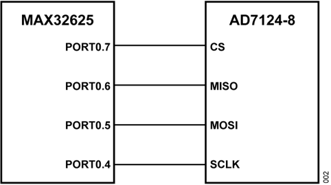
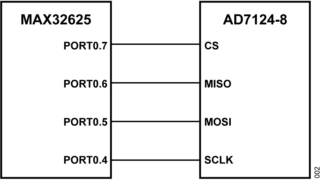
Table 1 lists the signals available on EVAL-AD7124-8 for quick prototyping. Note that it is important to check the microcontroller supply range. Figure 2 shows typical SPI connections between the MAX32625 and the AD7124-8.
MAX32625‐EVKIT
The MAX32625-EVKIT provides a convenient platform for evaluating the capabilities of the MAX32625/MAX32626 microcontroller. The MAX32625-EVKIT is all GPIOs available on the edge connectors. It is a fully functional system that is suitable for developing and debugging applications.
| JH1 Pin | Signal |
| GND | Ground |
| P0.7 | SPIM0 Port: SS |
| P0.6 | SPIM0 Port: MISO |
| P0.5 | SPIM0 Port: MOSI |
| P0.4 | SCK |
Companion Code
Typically, a project contains three source files and two definition files to interface the AD7124-8 with MAX32625-EVKIT.
| Source and Definition | Description |
| MXC32625.c | Set of functions to interface the MAX32625 to AD7124-8 via SPI |
| MXC32625.h | Functions and parameters definitions to interface the MAX32625 to the AD7124-8 via SPI |
| AD7124.c | Set of functions to configure the AD7124-8 |
| AD7124.h | Functions and parameters definitions to configure the AD7124-8 |
| Demo_main.c | Example code that calls some functions |
Demo Code Flowchart
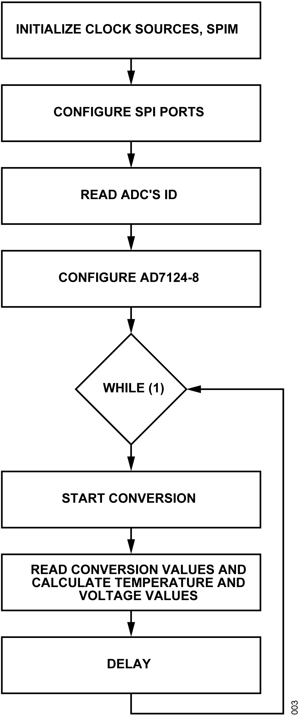
Figure 3 shows the demo code flowchart. The demo code configures the AD7124-8 in continuous conversion mode. In continuous mode, the ADC continuously performs conversions and places the result in the data register. RDY goes low when a conversion is complete. A software delay is used between each reading request for a conversion result.
AD7124-8 Functions
The four functions in Table 4 cover the main features of the AD7124-8. Parameters for these functions are defined in the header file (AD7124.h). All functions are based on SPIM interfaces of MAX32625.
| Function Name | Function Description |
| void AD7124_Reset (void) | Reset the AD7124-8 |
| uint32_t GET_AD7124_ID (void) | Return device ID of AD7124-8 |
| void AD7124_CH_init (uint8_t SamHz) | Configure ADC control, bipolar configuration, filter, sample rate, and excitation current |
| double CalculateRTDTemp (double r) | Calculate the RTD measurement result |
Use the Demo Code
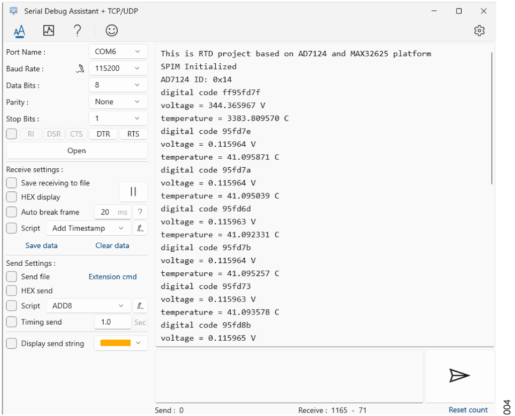
After connecting the boards, download the project to the MAX32625 and open a serial debug assistant application.
Check if the baud rate is 115200 bps. Figure 4 shows the measurement results on the serial port. Due to the inherent structure of ADC, the first sampled data is typically discarded.
