The Pmod specification allows for both 3.3V and 5V modules as well as various pin assignments. This module works with either 3.3V or 5V supply voltages and uses the SPI pin assignments as illustrated.
The power requirements are shown in Table 1. The currently supported platforms and ports are shown in Table 2.
Table 1. Power Requirements for the Corona Subsystem Reference Design
Power Type
Jumper Shunt
Power Name
Input Voltage (V)
Input Current (mA, typ)
Isolated power
JU1: 1–2
U3 VCAA
3.3
19.4
5
27.2
U1 VCC24V
12
13.6
24
14.5
Field power
JU1: 2-3
U3 VCAA
3.3
19.4
5
27.2
U1 VCC24V
12
8.2
24
8.2
Table 2. Supported Platforms and Ports
Supported Platforms
Ports
Nexys™ 3 platform (Spartan®-6)
JA1
ZedBoard™ platform (Zynq®-7020)
JA1
The Corona subsystem is an isolated, octal, digital input translator/serializer. The design includes an octal, digital input translator/serializer (MAX31911), an H-bridge transformer driver (MAX13256), and a six-channel digital isolator (MAX14850).
The MAX31911 (U1) industrial interface serializer translates, conditions, and serializes the 24V digital output of sensors and switches used in industrial, process, and building automation to CMOS-compatible signals required by microcontrollers. It provides the front-end interface circuit of a PLC digital input module. The device features integrated current limiting, lowpass filtering, and channel serialization. Input current limiting allows a significant reduction in power consumed from the field voltage supply as compared to traditional discrete resistor-divider implementations. Selectable on-chip lowpass filters allow flexible debouncing and filtering of sensor outputs based on the application. On-chip serialization allows a large reduction in the number of optocouplers used for isolation. For enhanced robustness with respect to high-frequency noise and fast electrical transients, a multibit CRC code is generated and transmitted through the SPI port for each 8 bits of data. The on-chip 5V voltage regulator can be used to power external optocouplers, digital isolators, or other external 5V circuitry.
The MAX13256 (U2) provides an isolated, functional insulation class power solution that accepts an 7.6V to 36V DC supply, and converts it to an isolated 7V to 36V DC supply with an off-the-shelf TGMR-501V6LF Halo® transformer with a 1:1 primary to secondary turns ratio plus an external on-board full bridge rectifier.
The MAX14850 (U3) accomplishes data isolation. On the Pmod side, the voltage supply can be 3.3V or 5V. (The Pmod power output for both the Nexys 3 and ZedBoard platforms is fixed at 3.3V.) On the MAX31911 side, the voltage supply is 5V. The combined power and data isolation achieved is 600VRMS.
To use the on-board isolation circuits, move the shunt on jumper JU1 to the 1–2 position and apply 7.6V to 36V DC supply on terminals TP3 and TP4. If the on-board isolation circuit is not required, move the shunt on jumper JU1 to the 2-3 position and apply 7V to 36V DC supply on terminals TP1 and TP2. See Table 1 for the jumper settings and the input current requirements.
Detailed Description of Firmware for Nexys 3 Platform
The Corona firmware design was developed and tested for the Nexys 3 development kit. The design targets a MicroBlaze™ soft core microcontroller placed inside a Xilinx® Spartan-6 FPGA.
The firmware is a working example of how to initiate the system and continuously read and display the MAX31911 register values. The simple process flow is shown in Figure 2. The firmware is written in C using the Xilinx SDK tool, which is based on the Eclipse™ open source standard. Custom Corona-specific design functions were created utilizing the standard Xilinx XSpi core version 3.03a. The SPI clock frequency is set to 3.125MHz.
Figure 2. The Corona firmware flowchart for Nexys 3 platform.
The complete source code is provided to speed up customer development. Code documentation can be found with the corresponding firmware platform files.
Detailed Description of Firmware for ZedBoard Platform
Figure 3. The Corona firmware flowchart for ZedBoard platform
The complete source code is provided to speed up customer development. Code documentation can be found with the corresponding firmware platform files.
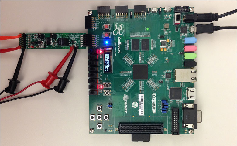
The following picture illustrates a test case for system operation on the ZedBoard platform. A 24V DC supply is applied on the TP3 and TP4 input power connectors. 24V is applied on channel 2 and channel 8 of the digital inputs. All other digital inputs are grounded. The OLED shows the register value as 0x8218. The LD7 (corresponding to input channel 8) and LD1 (corresponding to input channel 2) LEDs are lit up.
Figure 4. The Corona subsystem lab operation on the ZedBoard platform.
ARM is a registered trademark and registered service mark of ARM Limited.
Cortex is a registered trademark of ARM Limited.
Eclipse is a trademark of Eclipse Foundation, Inc.
Halo is a registered trademark of Halo Electronics, Inc.
MicroBlaze is a trademark of Xilinx, Inc.
Nexys is a trademark of Digilent Inc.
Pmod is a trademark of Digilent Inc.
Spartan is a registered trademark of Xilinx, Inc.
Windows is a registered trademark and registered service mark of Microsoft Corporation.
Xilinx is a registered trademark and registered service mark of Xilinx, Inc.
Search our knowledge base for answers to your technical questions. Our dedicated team of Applications Engineers are also available to answer your technical questions.