Abstract
Implementing tactile (haptic) feedback in consumer-electronic devices enhances the user's experience. It provides a sense of touch in a user-interface design and is the newest major interface on smartphones and other portable consumer-electronic devices. Several haptic technologies are available now, including but not limited to vibration motor actuation, piezoelectric actuation, and electro-active polymer actuation. This article explains the basics of piezoelectric-based actuation and how it offers a fast response time, thin profile, and low power, all of which are important in handheld applications.
A version of this app note was published by Planet Analog in two parts, part 1 appeared on November 17, 2010 and part 2 appeared on November 22, 2010.
Introduction
With the advent of touch screens replacing mechanical buttons on portable handheld consumer devices, the loss of tactile feedback has created a need for real-time feedback. Users are familiar with the "push to activate" feel of mechanical feedback to indicate a successful entry, for instance, on a keypad (Figure 1). Recently, the lack of good tactile feedback has fueled the demand for adding electrically-based tactile feedback systems.
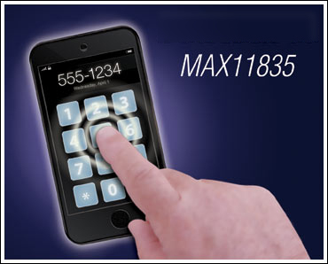
Figure 1. Push-to-activate software-based buttons.
One of the more promising approaches for real-time tactile feedback uses piezoelectric actuation, which has been available in a small number of consumer devices for several years. Piezo-based haptics offer several advantages including a fast response time, thin profile, low power, and a wide range of available piezo characteristics and mounting techniques.
Piezo Characteristics and Comparison
Piezos are available in many different shapes, sizes, thicknesses, voltage ranges, force, and capacitance ratings. They can be made into custom shapes for specific applications or packaging constraints, and are offered as single-layer or multilayer structures. Multiple piezos can be used to provide a stronger haptic response and more localized haptic feedback.
Piezo actuator applications for operation at or near resonance include:
- Vibration stimulation and cancellation
- Micropumps
- Microengraving systems
- Ultrasonic drilling/welding/knives/scalpels/scalars
Applications for operation well below resonance include:
- Tactile feedback
- Image stabilization
- Autofocus systems
- Fiber-optic alignment
- Structural deformation
- Wear compensation
The Basics of Piezo Operation
Well below resonance, the piezo can be modeled as a simple capacitor. Based on its configuration and physical shape, the piezo will change shape as a (DC) voltage is applied across its terminals (Figure 2).
Figure 2. Simplified piezo model.
Coulomb's law states that Q = CV. But in the piezo, C is not constant since the spacing between electrodes changes with applied voltage.
When voltage is applied to the piezo, the capacitance also changes because the distance between the electrodes is changing (Figure 3A). Displacement of the piezo is proportional to the electric field, and the electric field is a function of the electrode voltages and the distance between the electrodes. Applied voltage does maintain a reasonably proportional relationship with the force generated by the piezo actuator (Figure 3C).
Charge on the piezo capacitance holds a good proportional relationship with the displacement over most of the piezo actuator's range of motion. The displacement remains even if the electrodes are disconnected from the voltage source, except for the small leakage current found with any normal capacitor.
Figure 3. Displacement and force vs. applied voltage.
Force is proportional to applied voltage across the piezo (Figure 3). Force (versus time) is the dominant factor in tactile feedback; it determines a "good" user feel. Improving displacement can be accomplished using multilayer (stacks) of piezos.
A Piezo Model
The electromechanical system of motion in a piezo is modeled by series LRC in parallel with the primary dielectric capacitor, CP (Figure 4). Impedance rolls off like a capacitance until resonance is reached. Operating well below the resonant frequency, the piezo can be modeled as a simple capacitor, CP.

Figure 4. Piezo impedance vs. frequency.
Piezos can be used at the resonance frequency for free-running, fixed-frequency applications such as ultrasonic vibrators. However, piezo actuators used for tactile feedback are typically operated well below natural resonance.
For tactile feedback, the central issue is not the efficiency of driving the piezo, a concept often associated with audio applications. The main issue is about "feel," a human touch. Frequencies above a few hundred Hertz do not provide good tactile response and consume unnecessary power. Slew times faster than a few milliseconds provide a strong tactile feel, but produce an undesirable audible click.
Figure 5 shows a typical waveform for a good tactile feel. This waveform mimics the feel of a typical press and release on a mechanical button. The rising edge of the waveform, P0 to P1, provides the pressing-down tactile response, while the falling edge of the waveform, P2 to P3, provides the releasing tactile response. The time from P1 to P2 is the time that the user holds the "mechanical" button down; that interval will be determined by the user.
Figure 5. Example waveform for a “good” tactile feedback response.
When implementing a piezo-based tactile feedback system, one of the first decisions is whether to use single-layer or multilayer piezo actuators (Figure 6). A summary comparison of the two piezo types is shown in Table 1.
| Single-Layer Disc (SLD) | Multilayer Strip (MLS) | |
| Cost | Low | High |
| Capacitance load | Low | High |
| Voltage drive required | High | Low |
| Force | Good | Good |
| Mounting | Limited | Good |
| Production status | In production | Sampling/Low volume |
| Availability (sources) | Many | Few |
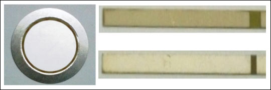
Figure 6. A 100VP-P single-layer piezo disc (SLD) at left; a 120VP-P (top right) and 30VP-P (lower right) multilayer piezo strip (MLS).
Design Decisions
A Single-Layer or Multilayer Configuration?
The information from Table 1 suggests using single-layer piezo actuators. They are more available and already in production volumes; multilayer piezos, while in production, are less available. Also, a single-layer piezo costs much less, a factor that becomes more important in solutions with more than one piezo. For example, several smartphones on the market have multiple single-layer discs mounted behind the display. A similar multilayer piezo solution would cost considerably more.
Discrete Components or a Single-Chip Solution?
One of the drawbacks of piezo-based haptics has traditionally been the complexity of the solution. Typical piezo-based solutions have used discrete components to implement the complete tactile feedback system; the extra discrete components included a microcontroller, flyback boost or charge-pump integrated circuit, flyback transformer or inductor, miscellaneous resistors, capacitors, diodes, and transistors. Compare that with DC-motor-based haptics which require few or no external components.
A single-chip monolithic haptic solution like the MAX11835 has several advantages over the older discrete designs: smaller printed circuit board (PCB) footprint, lower power, lower bill-of-materials (BOM) cost, and simple software support. Couple this with the low profile afforded by piezos, and the MAX11835 becomes an attractive solution for portable handheld devices.
Figure 7 presents the block diagram of a monolithic high-voltage haptic actuator controller.
Figure 7. Circuit diagram for a tactile feedback solution using piezo actuators.
The MAX11835 monolithic solution is optimized to provide:
- Single-layer and multilayer piezo actuator support
- User-definable, on-chip waveform storage (through the serial interface)
- On-chip waveform generator
- Built-in DC-DC boost controller
- Supply range that supports typical cell-phone battery voltages
- Small form factor to minimize PCB footprint
- Low-power operation
The Importance of Power Management
Piezo actuators by themselves require very little power compared to, for example, DC motor actuators. Nonetheless, there are other power factors to consider:
- The power taken from the main supply for each haptic event
- The waveform type for each haptic event
- The number of events per second
- The power consumed by the high-voltage boost circuit
Power-consumption measurements were performed on various piezo actuators and high-voltage capacitors using the MAX11835 haptic actuator controller. The MAX11835 plays back a stored waveform using a software-controlled, fly-back boost converter in a feedback loop. The test waveforms include a 100Hz sine wave and 20Hz ramp.
Figures 8 and 9A and 9B show the output of the MAX11835 driving a 175V 100Hz sine wave. The transformer's primary current is also plotted.
Figure 8. Output wave shape and boost power-supply current waveform from the MAX11835.
Figure 9A. Power vs. load for a 100Hz continuous sine wave.
Figure 9B. Peak boost power-supply current vs. load. Test conditions: frequency = 100Hz sine wave; boost power-supply voltage = 4.2V; boost supply decoupling = 10µF; 6:1 transformer.
A button press is a common feature. The waveform in Figure 10 uses a 40ms charge, 10ms discharge. The slow charge is imperceptible to the touch, and the rapid discharge feels like a mechanical button being depressed.

Figure 10. Simulated button press waveform.
Figure 11. Power vs. piezo voltage plot. Emulated button press using single and multiple disc piezos. The rapid increase in power above 180V is caused when the primary clamp in the MAX11835 turns on.
In Figure 11 the waveform is continuously running. The power scales down linearly as the duty cycle is reduced. There was no obvious difference in the piezo data between a mechanically loaded (at half-blocking force) and an unloaded piezo actuator.
Figure 12 presents the efficiency of the MAX11835's boost process, measured as energy delivered to the load and the energy drawn from the boost power supply (VBST).

Figure 12. Energy transfer efficiency: energy stored on load and energy drain in VBST. The rapid increase in efficiency above 180V is caused when the primary clamp in the MAX11835 turns on.
In Figure 12 it should be noted the efficiency increases as the load capacitance increases. This is due to the quiescent power required by the boost circuit.
MAX11835 Power vs. Motor Actuator Power
Power consumed by the MAX11835 compares favorably with motor-based actuators, including eccentric rotating mass (ERM), linear resonant actuator (LRA), and voice-coil types.
Motor-based actuators typically require low voltages (1.8V to 3V), but the currents can be fairly large. Also, the turn-on and turn-off characteristics of motors, especially ERM types, are less than ideal for the crisp haptic response necessary for emulated buttons and textures.
Comparative measurements were made on the actuators shown in Table 2 and Figure 13. Two types of measurements were collected, continuous operation and pulsed operation. Continuous operation is generally not a realistic case since many haptic responses are short lived, even for textured surface emulation.
| Actuator | ERM (Coin) | ERM (Bar) | LRA | Voice Coil | Piezo (SLD) |
| Size (mm × mm) | 12 × 2.85 | 15.5 × 4.7 | 10 × 3.9 | 12 × 47 | 44 (D) × 0.23 (T) |
| Turn-on time (ms) | ~85† | ~45† | ~12* | ~10* | — |
| Current | 60mA | 54mA | 56mARMS | 67mARMS | — |
| Power (continuous, mW) | 180 | 162 | 113 | 133 | — |
| RDC (Ω) | 25.3 | 39.6 | 35.4 | 30.1 | > 10M |
| Weight (g) | 1.4 | 1.4 | 0.9 | 15 | 0.4 |
| † With ~3V across the motor, the time to reach 50% of maximum RPM. * Approximately one half the resonant frequency at 2VRMS. |
|||||
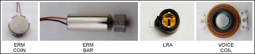
Figure 13. The actuators that were compared and yielded data for Table 2.
Figure 14 shows power dissipation for continuous operation. In this graph the piezos are driven with a continuous 100Hz sine wave at 180V amplitude. The other actuators are driven with either 3VDC or 2VRMS (LRA and voice-coil).
Figure 14. Continuous operation for the several actuators.
Figure 15 shows power dissipation for pulsed operation. For this graph the actuators were driven with a 50ms pulse that emulated a button press. The piezos actuators were driven to 180V amplitude and the other actuators were driven with either 3VDC or 2VRMS (LRA and voice-coil).
Figure 15. Pulsed operation for the several actuators.
Conclusions
Several conclusions can be drawn from the prior discussion. Clearly, single-layer, not multilayer, piezo actuators are a more attractive design solution at present for several reasons:
- Lowest cost
- Available from many sources
- In mass production
- Custom designs available
- Can be mounted behind or next to the LCD
Data show that power should be calculated for the haptic feedback circuit from the power supply. The waveform amplitude, type, and duration affect the resulting power usage and haptic response.
The number of events per second also affects the power usage. Consider scrolling or texture events vs. tapping or slow typing. Finally, normalizing the measurements to one event per second makes comparisons simple.
The author wishes to thank his colleagues at Maxim for supporting this project and collecting data on the various haptic actuators.
Related to this Article
Products
Product Categories
Latest Media 21


