Analog Tips– Decimation for ADCs
Wideband GSPS analog-to-digital converters (ADCs) offer many performance benefits to high speed acquisition systems. These ADCs provide a wide frequency spectrum of visibility. However, while some applications need a wideband front end, others also require the ability to filter and tune to a narrower spectrum band.
It is inefficient for an ADC to sample, process, and burn power to transmit a wideband spectrum when a narrow band is required. It is unnecessary to consume many FPGA transceivers to decimate and filter the wideband data in subsequent processing. High performance GSPS ADCs bring digital downconversion (DDC) within the ADC. This minimizes the data rate and complexity of system layout by lowering the number of JESD204B ADC output lanes.
Decimation is a method of observing only a periodic portion of the ADC samples, while ignoring the rest. The result is to reduce the sample rate of the ADC. For example, a decimate-by-4 mode would mean (total samples)/4, while all other samples are effectively discarded.
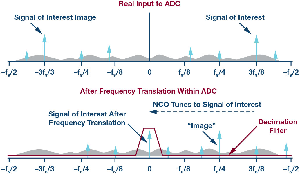
The ADC must also contain a numerically controlled oscillator (NCO), plus a filter and mixer component that is used as a companion to the decimation function. Digital filtering effectively removes the out-of-band noise from the narrowly defined bandwidth that is set by the decimation ratio. A digital tuning word to an NCO as a local oscillator provides a fractional divider of the sample rate with placement accuracy by the number of bits of resolution. The tuning word has the range and resolution to spectrally place the filter wherever it is needed.
The pass band of the filter should match the effective frequency spectrum width of the converter after the decimation. A distinct advantage of using DDCs is the ability to position the harmonics of the fundamental signal such that they fall outside the band of interest.
Digital filtering by the DDC filters the noise outside of a smaller bandwidth. The SNR calculation of an ideal ADC must account for the processing gain of the filtered noise. Using a perfect digital filter, the processing gain due to the filtered noise will increase by 3 dB for every power-of-two reduction in bandwidth:
Ideal SNR (with processing gain) = 6.02 × N + 1.76 dB + 10log10(fs/(2 × BW))

About the Authors
Related to this Article
Industry Solutions
Technology Solutions
Product Categories
{{modalTitle}}
{{modalDescription}}
{{dropdownTitle}}
- {{defaultSelectedText}} {{#each projectNames}}
- {{name}} {{/each}} {{#if newProjectText}}
-
 {{newProjectText}}
{{/if}}
{{newProjectText}}
{{/if}}
{{newProjectTitle}}
{{projectNameErrorText}}
Latest Media 21


