Why and How to Implement a Frequency Boost During a CCFL Lamp Strike on the DS3881/DS3882
Abstract
The DS3881 and DS3882 are controllers for cold-cathode fluorescent lamps (CCFLs) that backlight liquid crystal displays (LCDs) in automotive, industrial, and avionic applications. In these applications the CCFL lamps can require a high strike voltage. While several system design criteria affect the strike voltage, one criterion is easily modified to increase the lamp strike voltage: boosting the operating frequency during the lamp strike process.
This application note describes the need for increasing the CCFL controller operating frequency during lamp strike. The article also outlines a proven method that uses the DS3881 and DS3882 CCFL controllers to implement the frequency boost.
Need for a Frequency Boost During Lamp Strike
At cold temperatures, cold-cathode fluorescent lamps (CCFLs) require a higher strike voltage. At cold temperatures, the voltage required to initially strike (i.e., turn on) the lamps rises significantly. For more details about this requirement, see application note 3528, "CCFL Characteristics."
Several CCFL inverter system design criteria directly affect the strike voltage level:
- DC supply voltage
- Transformer turns ratio
- Amount of capacitance on the high-voltage transformer lead
- Operating frequency
Adjusting these parameters is not always straightforward. In most applications the DC supply voltage is a fixed constraint and cannot be changed. The transformer turns ratio is set to optimize efficiency and the lamp current waveform; changing the turns ratio can have negative consequences. The amount of capacitance can affect efficiency, and is itself somewhat variable since a portion of the capacitance is due to stray capacitance. The easiest of the above four parameters to change is the operating frequency.
In some applications, EMI or efficiency concerns can require that the lamp operating frequency be as low as possible. Typically, the lowest possible operating frequency is determined by the stability of the lit lamp, and is usually in the 40kHz to 50kHz range.
Before the lamp is lit, it is mostly capacitive. The system's resonant frequency is also higher than when the lamp is lit. A higher strike voltage can, therefore, be achieved by increasing the operating frequency during the lamp strike process.
As an example, the maximum lamp strike voltage for a particular system is shown in Figures 1 and 2. In this system, at 50kHz the maximum generated strike voltage is about 1100VRMS. If the strike frequency is increased to 66kHz, the maximum generated strike voltage is about 1600VRMS. Care must be taken not to increase the strike frequency too high, or the operating point will go beyond the resonant frequency and the resultant strike voltage will begin to decrease.

Figure 1. At 50kHz, the generated strike voltage is about 1100VRMS.

Figure 2. At 66kHz, the generated strike voltage is about 1600VRMS.
Implementing a Strike Frequency Boost
With a few external components, the DS3881 and DS3882 CCFL controllers can increase the operating frequency during lamp strike and thereby increase the strike voltage level. These controllers can operate with a microcontroller (software control) or without a microcontroller (hardware control). Figures 3 and 4 outline the extra components needed to implement the strike frequency boost.
On the DS3881 and DS3882, the lamp driving frequency is determined by the value of an external resistor tied between the LOSC pin and ground (R1 in Figures 3 and 4). The lamp frequency is set by the following equation:
Lamp Frequency (lamp run) = 1.6E6/R1
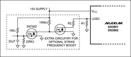
Figures 3 and 4 outline the external circuitry needed to increase the lamp frequency during lamp strike. By adding a shunt resistor (R2) during lamp strike, the lamp frequency will increase according to the following equation:
Lamp Frequency (lamp strike) = 1.6E6/[(R1×R2)/(R1+R2)]
In Figure 3, an external microcontroller will turn on a n-channel MOSFET during the strike process. In this case, the microcontroller can use the DS3881/DS3882's internal status registers to determine when the lamp is struck, and then disable the MOSFET to allow the system to run at a lower frequency.
In Figure 4, it is assumed that lamp strike occurs during power up when 5V is applied to the DS3881 and DS3882. The external circuitry uses the 5V supply to charge a RC timer that will increase the operating frequency for a short period during lamp strike.
In both control schemes, the exact timing of the strike process is not critical. The DS3881 and DS3882 CCFL controllers are specified to operate from 40kHz to 100kHz. It is thus always safe to increase the strike voltage because the controllers will limit the maximum output voltage to a safe operating point. As long as the strike frequency is less than 100kHz, the system can be operated without any concern for many seconds before returning to the nominal lamp run frequency.

Figure 3. System configuration for implementing a strike frequency boost using the DS3881/DS3882 controllers under software control.

Figure 4. System configuration for implementing a strike frequency boost using the DS3881/DS3882 controllers under Hardware Control.
An Application Example
The system with the lamp strike voltages shown in Figures 1 and 2 will be used as an application example. The nominal lamp run frequency will be 50kHz and the higher strike frequency will be 66kHz.
The values for R1 and R2 first need to be calculated with the following equations:
R1 = 1.6E6/50kHz = 32kΩ
(R1xR2)/(R1+R2) = 1.6E6/66kHz; substituting in R1 yields R2 = 100kΩ
The LSYNC pin on the DS3881 and DS3882 can be used to determine the operating frequency of the CCFL controller. Figure 5 shows the ramp up in frequency when R2 is enabled. It takes less than 200µs for controller to reach the higher strike frequency. In this application example, the strike time was set to about 600ms. Figure 6 shows that the controller is still operating at the higher 66kHz frequency after 600ms, but returns to the nominal lamp run frequency of 50kHz after 610ms.

Figure 5. Frequency ramp during strike with the DS3881/DS3882.

Figure 6. DS3881/DS3882 controllers return to nominal lamp run frequency.
Related to this Article
{{modalTitle}}
{{modalDescription}}
{{dropdownTitle}}
- {{defaultSelectedText}} {{#each projectNames}}
- {{name}} {{/each}} {{#if newProjectText}}
-
{{newProjectText}}
{{/if}}
{{newProjectTitle}}
{{projectNameErrorText}}


