Ultrathin Dual 2.5A or Single 5A μModule Regulator Fits on the Backside of PCBs, Allowing Space on the Topside for Digital ICs
Ultrathin Dual 2.5A or Single 5A μModule Regulator Fits on the Backside of PCBs, Allowing Space on the Topside for Digital ICs
by
Sam Young
Nov 23 2015
Design Note 546: Introduction
The top side of a typical system board, such as a PCIe card, is densely populated with FPGAs/ASICs/microprocessors, transceivers, connectors, memory ICs and DC/DC regulators, while the backside is often unused. This is a common side effect of the significant difference in top vs back side height restrictions, where board specifications may allow topside devices to reach a few centimeters, but restrict backside packages to less than 2.3mm. What if functions usually found on the topside, such as DC/DC regulator circuits could be thinner and moved to the bottom? Real estate on top would be available for expanding memory or enhancing the board/given the additional top side space.
The LTM4622 is a dual 2.5A, or single two-phase 5A, output step-down μModule® (power module) regulator in a 6.25mm × 6.25mm × 1.82mm ultrathin LGA package. At nearly the height of a soldered down 1206 case size capacitor, its ultralow height allows mounting on the backside of a PCB, freeing space on the topside of the board. The thin profile allows it to meet demanding height restrictions such as those required by PCIe and advanced mezzanine cards in embedded computing systems.
Flexible Dual Supply in a Simple <0.5cm2 Footprint
The LTM4622 has a wide input voltage range of 3.6V to 20V, and it can be configured to operate down to 3.1V for operation from a 3.3V input supply. It regulates two voltages for a compact multi-rail solution, where each output can supply up to 2.5A (3A peak) and is capable of precisely regulating 0.6V to 5.5V within ±1.5% maximum total DC output voltage error over line, load and temperature. For higher output current up to 5A, simply tie the outputs for current sharing.
The LTM4622 requires only three ceramic capacitors and two resistors to complete a solution occupying less than 1cm2 single-sided or 0.5cm2 on a doublesided PCB.
Figure 1 shows the LTM4622 circuit in a typical dual output application, illustrating the compact solution size. Efficiency and power loss for the circuit operating at 12V input are shown in Figure 2.


Reliable High Performance Regulation
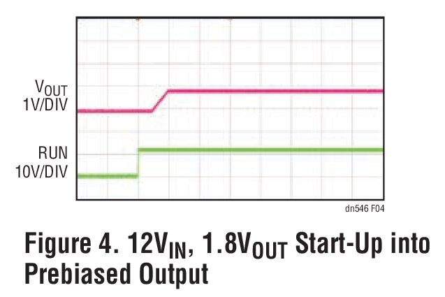
The LTM4622 features a controlled on-time current mode architecture for a fast transient response and loop stability over a wide voltage range. It provides short-circuit, overvoltage and overtemperature protection and ensures monotonic output voltage ramping with tracking, soft-start and the ability to start into a prebiased output. It places no limitation on input supply slew rate.
Figures 3 and 4 demonstrate the fast transient and prebias start-up performance for the 1.5V output rail of the Figure 1 circuit.

![Figure 3. Load Step Response (Figure 1 Design) [12V Input, 1.5V Output, 1.25A to 2.5A]](/en/_/media/analog/en/landing-pages/technical-articles/ultrathin-dual-2-5a-or-single-5a-module-regulator-fits-on-the-backside-of-pcbs-allowing-space-on-t/34181.png?la=en&rev=79d46bb5ec5f46278f7802a71ea58193)

Parallel Operation for Higher Current Applications
The LTM4622's current mode architecture yields reliable cycle-by-cycle current monitoring, allowing its two outputs to be combined in parallel for load currents up to 5A.
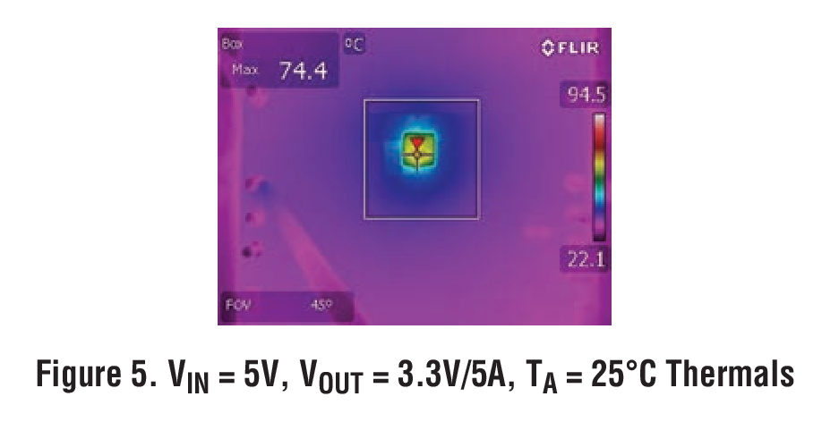
Figures 5 and 6 demonstrate the thermal and current sharing performance of the LTM4622 when configured for two-phase current sharing, generating a 3.3V output at 5A (16.5W) from a 5V input.


![Figure 6. Accurate Current Sharing Over the Entire Load Range [VIN = 5V, VOUT = 3.3V at 5A]](/en/_/media/analog/en/landing-pages/technical-articles/ultrathin-dual-2-5a-or-single-5a-module-regulator-fits-on-the-backside-of-pcbs-allowing-space-on-t/34183.png?la=en&rev=7537dc5ddf7940d4936891d003190c5c)
Mirrored Layout for Smaller PCB but Higher Power
The LTM4622’s pin configuration is organized symmetrically. So for higher current applications where two LTM4622s can be paralleled for up to 10AOUT, one device can be on the topside of PCB and the other mirrored on the bottom side, minimizing PCB area while increasing output power and power density.
Conclusion
The ultrathin LTM4622 makes it possible to put a high performance regulator for single and multi-rail applications on the backside of a PCB, or into tight spaces on the topside. Its wide operating range, features and compact solution size make it a highly flexible and robust solution.
About the Authors
Sam Young is a senior applications manager for Analog Devices, supporting μModule® regulator products and LTpowerCAD. He has over 10 years of experience in supporting regulator designs for for a broad range of application...
Related to this Article
Products
Resources
{{modalTitle}}
{{modalDescription}}
{{dropdownTitle}}
- {{defaultSelectedText}} {{#each projectNames}}
- {{name}} {{/each}} {{#if newProjectText}}
-
 {{newProjectText}}
{{/if}}
{{newProjectText}}
{{/if}}
{{newProjectTitle}}
{{projectNameErrorText}}
Latest Media 21


