Trends in Three-Phase Energy Metering: New Innovative Isolated ADC Architecture Enables Three-Phase Energy Meters with Shunts
Trends in Three-Phase Energy Metering: New Innovative Isolated ADC Architecture Enables Three-Phase Energy Meters with Shunts
Nov 1 2012
Idea in Brief
Traditional three-phase energy meters use current transformers (CTs) to sense phase and neutral currents. One advantage of CTs is the inherent electrical isolation they provide between the power line operating at hundreds of volts, and the meter ground, typically connected to the neutral. CTs can achieve good linearity and have the flexibility to measure a wide range of currents through adjustment of turn ratios and burden resistors. However, they also have some disadvantages for use in electricity meters. First, the magnetic core of CTs can be saturated by external dc magnetic fields. Extremely powerful rare earth dc magnets are now easy for the average homeowner to obtain and apply for meter tampering. Second, CTs can also be saturated by power electronic equipments such as direct-connect inverters for distributed solar generation that produce dc currents on the line. Manufacturers can counter these two effects through shielding and the use of dc tolerant CT; however, this adds cost, and some suggest that for every such CT, one can find a permanent magnet to tamper it. Third, CTs introduce a measurement phase delay that is dependent on the frequency of line currents. If only the fundamental component of line current is of interest, it is relatively easy to compensate this delay. However, measuring harmonic content is becoming increasingly important, and it is very difficult to compensate the delays of the fundamental and all harmonics combined.
Other current sensors are used less frequently in three-phase meter applications, including di/dt sensors such as Rogowski coils or Hall-effect sensors. While these can provide advantages in some applications, they come with their own challenges. For example, Rogowski coils have excellent linearity and can sense very high currents but they can’t sense DC signals. From a tamper perspective, they can be susceptible to high ac magnetic fields. Hall-effect sensors require active compensation of offset over temperature, have worse accuracy performance and are inherently susceptible to magnetic fields.
Here is a summary of the pros and cons of each sensing technology:

Shunts and Three-Phase Energy Metering
The use of resistive shunts in single-phase meters has rapidly increased in recent years, driven by cost, magnetic immunity, and size benefits. In many cases, these single-phase meters are referenced to the line voltage and, thus, avoid the need for additional isolation. In three-phase meters, the challenge of creating an isolation barrier between each shunt and the core of the meter must be addressed. Heating issues also become an issue, typically limiting the use of shunts to meters with maximum currents of 100 A or less.
Let’s first consider the Phase A of a three-phase system and its load. Imagine a shunt is used to sense the phase current (Figure 1).
|
|

Figure 1. Phase A Current and Voltage Sensing When the Phase Current Is Sensed with a Shunt.
It is exactly a single-phase energy meter configuration: the shunt is placed in the power line, and a voltage divider senses the phase to neutral voltage. The voltages across the shunt and the voltage divider are sensed by an analog-to-digital converter (ADC). The ground is the pole of the shunt shared with the voltage divider. The single-phase meters are mostly residential, and their maximum current is generally lower than 120 A. This limit and the low cost make the shunts the most commonly used current sensors in single-phase energy metering.
When this scheme is repeated across all three phases, each ADC has its own ground (Figure 2).
|
|

Figure 2. Three-Phase Current and Voltage Sensing When the Phase Currents Are Sensed with Shunts.
As the microcontroller (MCU) that manages all of them is placed on the same potential with the neutral line, to make the communication between the ADCs and the MCU work, one has to isolate the data channels. Then, every ADC has to have its own isolated power supply (Figure 3).

Figure 3. Three-Phase Meter with Shunts, Separate Power Supplies, and Isolated Communication.
This meter architecture is already in use: two channel ADCs transmit information serially to the MCU across the isolation barrier using optocouplers or chip-scale transformers. The isolated power supplies are built using stand-alone components or isolated dc-to-dc converters that use chip-scale transformers.
Ideally, all the phase currents and voltages should be sampled simultaneously, so one can use their instantaneous values for a comprehensive three-phase analysis. But the ADC readings on every phase are fully independent from the others as there is no ADC synchronization. This is the first limitation of this architecture. Energy meters that use current transformers or Rogowski coils do not have such a problem, as they may use a metering analog front end (AFE) that reads all the phase currents and voltages simultaneously.
Another problem with this architecture is the high component count: an MCU, three ADCs, three multichannel data isolators, and four power supplies. Meters that use CTs do not have such a problem, as a circuit board usually has an MCU, a metering AFE, and one power supply.
Then, how can one create a meter that has the benefits of shunts, with the lowest number of components for this architecture (i.e., one MCU, one power supply, and three ADCs), and sample all the phase currents and voltages simultaneously?
The Isolated ADC Architecture
The answer to this challenge is to create a chip that integrates at least two ADCs, one isolated dc-to-dc converter and data isolation and has technology that allows the ADCs belonging to different chips to sample data simultaneously (Figure 4). The power supply VDD of the MCU powers also this chip. An isolated dc-to-dc converter using chip-scale transformer technology provides the isolated power to the first stage of the ADCs. One ADC senses the voltage across the shunt, and a second one senses the phase to neutral voltage using a voltage divider. The ground determined by one of the shunt’s poles is the ground of the isolated side of the chip. The ADCs are sigma-delta and only the first stage is placed on the isolated side of the chip. The bit stream coming out of the first stage passes through the chip-scale transformers that constitute the isolated data communication channels. The bits are received on the nonisolated side of the chip, filtered, put into 24-bit words, and provided at a SPI serial port.
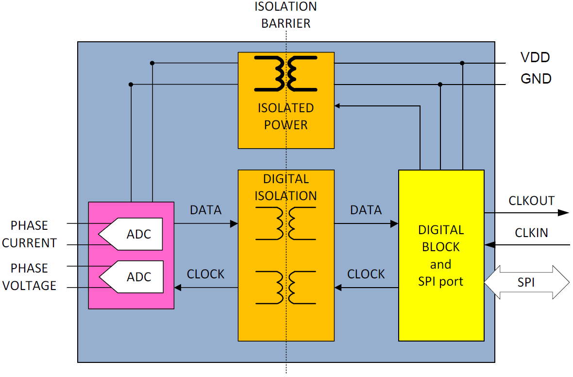
Figure 4. New ADC Architecture that Includes Two-Channel ADCs, Data Isolation, and One Isolated DC-to-DC Converter.
The chip-scale transformer technology is the most important contributor to this new ADC architecture: the Analog Devices patented iCoupler® digital isolators have better reliability over optocouplers, smaller size, lower power consumption, higher communication speed and better timing accuracy. But this is not enough. Isolated sigma-delta modulators have been on the market for a long time, using either optocouplers or chip-scale transformers. The most important contribution of the chip-scale transformer technology is the companion isoPower® isolated dc-to-dc converter that may be integrated with the ADCs, the digital block, and the isolated data channels into the same surfacemount, low-profile package.
As the core of the chip scale transformers is air, the iCoupler digital isolators and the isoPower isolated dc-to-dc converter are not affected at all by permanent magnets, making this side of the energy meter completely immune to dc magnetic tampering. The transformers are highly immune to ac magnetic fields too. The area of the coils is so small that one would have to create a 10 kHz magnetic field of 2.8 T to affect the isoPower coil behavior. To put it in other words, one would have to create a 10 kHz current of 69 kA through a wire and bring that wire 5 mm away from the chip in order to affect the behavior of the chip-scale transformers.
The information is transmitted across the isolation barrier using very high frequency PWM pulses. This creates high frequency currents that propagate in the circuit board causing edge and dipole radiation.
To make the interface with the MCU as simple as possible, the digital block of the chip executes the filtering of the bit stream coming from the first stage and creates 24-bit ADC outputs through simple slave SPI serial port. As the energy meter has one isolated ADC on every phase, the challenge of obtaining coherent ADC outputs remains. The first stage of the ADCs may sample in the same exact moment on all phases if they function with the same clock. This is easy to accomplish if the CLKIN signal from Figure 4 is generated from the MCU. An alternative is to use one crystal to create a clock for one chip and use the buffered CLKOUT signal to clock all the other isolated ADCs. All the isolated ADCs are controlled to generate their ADC outputs at the same exact moment. Now the energy meter can execute an accurate and comprehensive three-phase analysis using shunts for current sensing.
Figure 5 presents a three-phase meter using three isolated ADCs (ADE9112 or ADE9113). The meter has only one power supply that powers the MCU and the isolated ADCs. The MCU uses a SPI interface to read the ADC outputs from each ADE9112 or ADE9113.

Figure 5. Three-Phase Meter Using the New Isolated ADCs.
The preceding description presumes the use of an external MCU to implement the metrology calculations. For meter manufacturers who prefer a solution that includes metrology, it is possible to couple the isolated ADCs (ADE7932 or ADE7933) to an IC that executes all the metrology calculations, (ADE7978), as shown in Figure 6.

Figure 6. Three-Phase Meter Using the New Isolated ADCs and Metrology IC.
New Products Based on this Architecture
This architecture has already been designed into a new family of Analog Devices products: ADE9113, ADE9112, ADE7933, and ADE7932. Figure 7 presents the block diagram of the ADE9113. It is very similar to Figure 4 but has an additional ADC channel that senses an auxiliary voltage. The auxiliary voltage may be the voltage across a breaker or to sense a temperature senor. The ADE9112 is a variant that does not have the auxiliary voltage measurement.

Figure 7. The New ADE9113 Isolated ADC Based on this Architecture.
Conclusion
A novel isolated ADC architecture has been presented. It contains an isoPower isolated dc-to-dc converter that uses the MCU supply to power the first stage of a multiple channel sigma delta ADC across the isolation barrier. The bit streams coming out of the ADC pass through the iCoupler data isolators and are received by a digital block. This block filters them and creates 24-bit ADC outputs that can be read using a simple SPI interface. One ADC can measure the current that passes through a shunt, a second one can measure the phase to neutral voltage using a voltage divider and a third one can measure an auxiliary voltage. It enables three-phase energy meters using shunts, assuring complete immunity to dc and ac magnetic fields and current sensing without any phase shift, while lowering the overall system cost. The small form factor ensures a very small circuit board, with very few components to assemble. The integrated isoPower chip-scale transformers are designed for a known ADC load to minimize radiated emissions and has been tested to pass CISPR 22 Class B standard.
Of course, current sensing using shunts is not limited to energy metering. Power quality monitoring, solar inverters, process monitoring and protective devices can also all benefit from this new ADC architecture.
About the Authors
Petre joined ADI in 2000 and has held a variety of systems engineering roles within Motor Control and DSP organizations. He graduated with an Electrical Engineering degree from Polytechnic Institute in Bucharest, Romania i...
Tristan has been managing the Energy Metering portfolio at ADI since 2021. He has worked in the semiconductor industry for over a decade, across various Program and Product Marketing responsibilities. Tristan completed his...
Related to this Article
Products
RECOMMENDED FOR NEW DESIGNS
Isolated, Sigma-Delta ADCs with SPI
RECOMMENDED FOR NEW DESIGNS
Isolated, Sigma-Delta ADCs with SPI
PRODUCTION
3-Phase Metrology IC for Polyphase Shunt Meters
Industry Solutions
Product Categories
{{modalTitle}}
{{modalDescription}}
{{dropdownTitle}}
- {{defaultSelectedText}} {{#each projectNames}}
- {{name}} {{/each}} {{#if newProjectText}}
-
 {{newProjectText}}
{{/if}}
{{newProjectText}}
{{/if}}
{{newProjectTitle}}
{{projectNameErrorText}}
Latest Media 21


