The Importance of Being Earnest (About Reading from an ADC on the I²C Interface)
Abstract
This application note discusses the need for care when reading multibyte data over the I²C-compatible interface. Pitfalls of reading one byte at a time are discussed, with some concrete examples. The article also describes the proper way to handle such a data transfer.
Introduction
The I²C-compatible, two-wire interface is a powerful mechanism for interfacing microcontrollers or microprocessors to low-speed peripherals, such as a peripheral with an integrated analog-to-digital converter (ADC). The most basic form of communicating over this bus (i.e., writing/reading a single byte at a time to/from a slave's register) is quite straightforward. However, limiting oneself to this approach for the sake of simplicity has some pitfalls.
2 Bytes of Data over a 1-Byte Channel
As with any other digital interface to peripherals (especially sensors), we need to read the correct data from the device's internal registers. This is especially critical when the data in the register changes during the course of the read. Data can change if the ADC runs its conversions or updates the registers while the data is being transferred. Many devices have an internal buffer (not usually accessible from the outside) that contains the most recent results of a conversion. The device updates the so-called "customer-accessible" registers with the new data when there is no I²C activity.
The I²C protocol transfers 1 byte of data at a time. Therefore, if the total amount data of interest is longer than 8 bits and the transfers are not handled properly, problems can occur. For example, the MAX44000's ambient light sensor (ALS) data register can have up to 14 bits of data (plus 1 bit indicating overflow, which means the counts/lux setting should be increased).
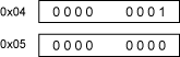
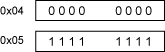
| REGISTER | B7 | B6 | B5 | B4 | B3 | B2 | B1 | B0 | REGISTER ADDRESS |
| ADC High Byte (ALS) | OFL | 0x04 | |||||||
| ADC Low Byte (ALS) | 0x05 | ||||||||
We cannot directly read all of ALSDATA[13:0] over I²C, so we must first read the contents of register 0x04, then read the contents of register 0x05, and concatenate the data in at least a 16-bit register. However, we must take care as to how we read this data. It is possible to simply do two single reads terminated by a STOP (P) condition, as shown in Figure 1.
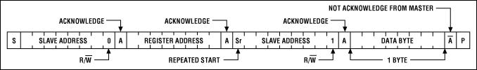
Figure 1. Single byte read.
This approach has a fatal flaw. Specifically, sending the STOP condition signals the device to return to updating the "customer-visible" registers. Thus, after getting data from register 0x04, the 14 bits of data may, in fact, be updated before register 0x05 can be read. There are several cases where this flaw can have the potential for disastrous consequences.
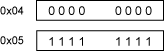
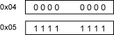
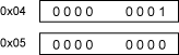
An example would be if the light levels are at a certain level, with the MAX44000 ambient light sensor in 10-, 12-, or 14-bit mode. Suppose the levels were hovering in an area so that the 14 bits in registers 0x04 and 0x05 would be at either 255 or 256 total counts, perhaps due to slowly increasing light or some small amount of noise. Consider the three situations in Table 2.
| State of Registers During First Byte Read (Read 0x04 Only) |
State of Registers During Second Byte Read (Read 0x05 Only) |
Result (14 Bit) |
 |
 |
 |
 |
 |
 |
 |
 |
 |
In the last two situations, instead of reading 255 or 256, we read either 0 or 511. This is a huge problem. It occurs because the data in registers 0x04 and 0x05 was updated between the first and second read, after a STOP condition was sent. In the first problematic situation, the first byte was read properly. But by the time the second byte was read, the data read 256 total counts, where the lowest byte was zero. Therefore we got a reading of zero from the device. In the second problematic situation, the data was also 256 counts total. This appeared to become 511 counts, due to the data decreasing by one count after the STOP condition was sent, but before the second byte was read. See Figure 2 for a sample of how many times this occurs over multiple reads.
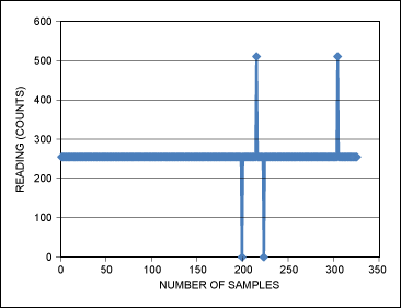
Figure 2. Actual readings with single byte read over many samples.
This issue is easily avoided by reading 2 bytes at a time, as illustrated in Figure 3. This is done by sending a REPEATED START instead of a STOP condition after the first data byte is read, and is fairly straightforward to implement. By reading 2 bytes, we prevent the part from performing more I²C register updates, even though we send the same number of bits between the two devices overall.
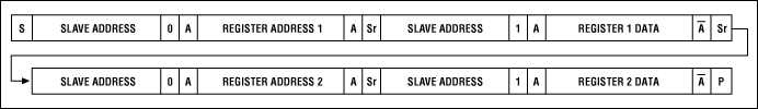
Figure 3. Illustration of a 2-byte read.
The above example applies to the MAX44000 and MAX44009, which do not autoincrement the register pointer when doing multiple reads. Your device may behave differently, but the principle is always the same. This is easily extended to reading N bytes. For some ideas on how to implement this in C, see application note 3588, "Software I²C Driver for the MAXQ2000 Microcontroller."
{{modalTitle}}
{{modalDescription}}
{{dropdownTitle}}
- {{defaultSelectedText}} {{#each projectNames}}
- {{name}} {{/each}} {{#if newProjectText}}
-
 {{newProjectText}}
{{/if}}
{{newProjectText}}
{{/if}}
{{newProjectTitle}}
{{projectNameErrorText}}
Latest Media 21


