Solving Industry 4.0 Challenges with Software Configurable I/O
Solving Industry 4.0 Challenges with Software Configurable I/O
Jul 18 2022
Abstract
This article presents a software configurable input/output (I/O) device and its dedicated isolated power and data solution that helps solve the challenges in bridging the legacy analog signaling to the Industrial Ethernet. This article explains the benefits of channel flexibility, fault detection, and diagnostic capabilities that are inherent to the software configurable I/O device. System-level evaluation results are also presented to showcase the overall benefits of the system solution including system robustness and power dissipation.
Introduction
Advances in Industrial Ethernet have enabled smart, connected manufacturing in factories. Field instruments must be connected to the Ethernet domain using legacy analog signaling (that is, 4 to 20 mA, 0 V to 10 V). This presents challenges for fixed function I/O modules. System designers need to design multiple modules to cover the different sensors and actuators. However, some of the channels in a fixed function module may be unused and in surplus. A software configurable I/O module allows for an efficient use of all channels in an I/O system. Crowded cabling could cause incorrect connections of sensors and actuators to these fixed function I/Os. Debugging and fixing these faults are time-consuming and require manually reconnecting the loads to the I/O channels.
A software configurable I/O system provides a seamless transition from legacy analog signaling to the Industrial Ethernet domain. Software configurable I/O devices can provide any function (analog I/O, digital I/O, RTD) on any channel through remote configuration, which helps ease commissioning. This flexibility combined with diagnostics capability allows for remote troubleshooting, thus saving time and effort for technicians. Figure 1 shows the evolution of industrial connectivity from legacy analog signaling to smart, digitally connected sensors with software configurable I/O enabling a seamless transition.


Figure 1. A software configurable I/O bridging legacy devices to the Ethernet.
Analog Devices’ AD74413R software configurable I/O coupled with the ADP1032 2-channel isolated micropower management unit (µPMU) is one example of a robust software configurable I/O solution. The AD74413R is a quad-channel software configurable I/O that is equipped with automatic fault detection and diagnostic capabilities. The ADP1032 is tailored to the AD74413R to provide isolated power and data channels, which allow for a compact and isolated software configurable I/O system.
Channel Flexibility
For various industrial applications with varying I/O requirements, system designers need a flexible system that can be quickly configured to adapt to the demand. The four channels of the AD74413R can be configured into various input and output modes such as:
- High impedance
- Voltage input
- Voltage output
- Externally powered current input
- Loop-powered current input
- Current output
- Digital input logic
- Loop-powered digital input
- RTD measurement
A single set of external discrete components is required to support any function on any of the four channels, offering full flexibility. If an actuator or sensor is miswired, the channel can be reconfigured with a single SPI.
Having all functions available in a single package requires fewer components in the hardware design, which leads to:
- Lower assembly and test costs
- Higher reliability and easier debugging
- Simplified procurement
- Higher channel density compared to discrete implementations of universal I/O
Figure 2 shows the required external components to support all functions of the AD74413R, regardless of the connected load.


Figure 2. AD74413R with required external components for all functions.
Fault Detection and Diagnostic Capabilities
The AD74413R is equipped with automatic fault detection and different diagnostic functions to help in fault isolation. The ALERT pin is asserted and can be used to interrupt the microcontroller during a fault condition. Then users can interrogate an alert register to determine the exact cause of the fault. Users can also enable diagnostic signals to further diagnose the identified fault.


Figure 3. Software configurable I/O fault detection.
These are the faults that can be detected by the AD74413R:
- Reset
- Calibration memory error
- SPI CRC error
- ADC error
- Power supply error
- Temperature error
- Open-circuit/short-circuit error
These capabilities allow users to remotely troubleshoot any faults occurring in their system. In many existing systems, sensors and actuators may be located far away from the control room and in potentially hazardous areas. In addition, crowded cabling may also make it difficult to determine which cables are connected to which sensor or actuator, making it cost prohibitive and timeconsuming to physically rewire these systems. The AD74413R modules provide configurability and diagnostics to determine which sensor or actuator is connected to a particular channel.
Isolated Power and Data Solution
Discrete Implementation
A discrete isolated power solution for the AD74413R requires multiple components, as shown in Figure 4. Separate isolators are used to provide power and data isolation. This creates the problem of having a large board area due to the increased number of components.


Figure 4. Block diagram of the AD74413R discrete power solution.
ADP1032 Solution
Figure 5 shows the block diagram of the AD74413R powered by the ADP1032. The ADP1032 satisfies the requirement for isolated power and data channels by having two isolated and regulated rails and seven data isolation channels all in one package. This provides a board area reduction of ~3× compared to having discrete power and data isolation solutions. This allows customers to increase the overall channel density in their modules. The four SPI signals of the AD74413R use the high speed isolated data channels of the ADP1032, which are optimized for low propagation delays of 15 ns, supporting SPI clock rates up to 16.6 MHz. The low speed isolated data channels are used where timing is not critical like the LDAC, RESET, and ALERT signals.


Figure 5. A block diagram of the AD74413R powered by the ADP1032.
System Robustness
The AD74413R system solution is designed to be robust in harsh industrial environments and offers the following protection features:
- A TVS on the screw terminals (for protection against surge events)
- The screw terminal facing pins are tolerant to ±50 V DC and higher (for transient events)
- Power cannot be delivered to the device from the screw terminals in a miswire event
An SPI CRC and SCLK count feature ensures no erroneous SPI transactions occur. In addition, the ADP1032 provides isolated power to the two positive rails of the AD74413R and isolates the data of the four SPI signals and three GPIO signals. The ADP1032 has a basic isolation of up to 300 V for pollution degree 2. The galvanic isolation in the power and data channels of the ADP1032 protects the system from high voltage transients, reduces noise from ground loops, and creates physical safety.


Figure 6. ADP1032 + AD74413R software configurable I/O System robustness.
The ADP1032 and AD74413R are measured and verified as a complete system and conform to the CISPR 11 Class-B radiated emission levels with greater than 6 dB margin, as shown in Figure 7.

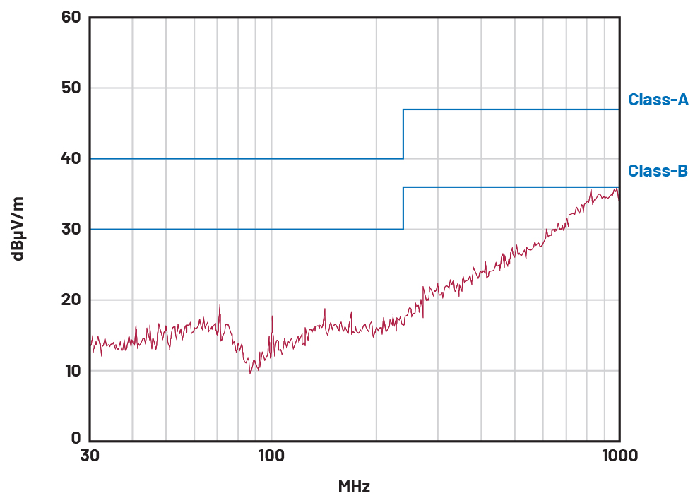
Figure 7. AD74413R + ADP1032 radiated emission passing CISPR Class-B.
Power Dissipation
Having a flexible multichannel system poses a trade-off on the system power dissipation because each channel of the AD74413R software configurable I/O can be configured to various modes while the power supply for the AD74413R sticks to a single output voltage. The designer must pick the highest AD74413R AVDD supply voltage so it can support the worst-case condition with consideration to the required voltage headroom and the load characteristics, to ensure the proper operation of each mode. Consider the use case where the AD74413R is in current output mode, with a load resistance of 600 Ω, and the input current range is up to 20 mA. This translates to a maximum output voltage of 12 V on the screw terminals. As per the AD74413R data sheet, the required headroom voltage for the current output mode is 4.6 V. Adding the headroom voltage to the maximum output voltage results in 16.6 V, which is the required minimum AVDD supply for the AD74413R in current output mode. The same AVDD supply voltage computation should be done for other input and output modes and the highest resulting AVDD voltage must be used as the output of the ADP1032 VOUT1.
The ADP1032 + AD74413R system power dissipation can be calculated by treating the whole system as a black box and just subtracting the output power (POUT) delivered to the load from the input power (PIN) supplied to the system as shown in Figure 8. The system power dissipation will include the losses from the ADP1032 power conversion, AD74413R quiescent current, the digital channel isolators’ quiescent currents, and the losses in the AD74413R output path especially the headroom required. Figure 9 shows the system power dissipation with all four channels of AD74413R configured with the same mode of operation and with the same load characteristics. In this example, the ADP1032 VOUT1 output that supplies the AD74413R AVDD was set to 16.6 V, which is assumed to support all the different modes of operation with the predefined loads and input and output conditions. The input supply for the ADP1032 is 24 V. System power dissipation is worse for the current output mode, which is still less than 1 W for four channels operating at full-scale output, as shown in Figure 9. Power dissipation is highly affected by the level of input and output of the AD74413R as well as the loads.


Figure 8. An ADP1032 + AD74413 black box illustration.


Figure 9. AD74413R + ADP1032 system power dissipation for various operating modes and loads (all four channels configured the same), ADP1032 input supply = 24 V.
Care must be taken when choosing the input supply to the ADP1032 (VINP). The choice of ADP1032 VINP will determine the maximum output current of the ADP1032 that will be supplied to the AD74413R. Figure 10 shows the maximum output current of the ADP1032 for various VOUT1 settings across the VINP range. The chosen input supply for the ADP1032 must be able to support the current demand of the AD74413R in a worst-case condition like in the case of the output current mode where all four channels were driving a max output current of 20 mA.


Figure 10. ADP1032 VOUT1 maximum output current at various output voltages across input supply voltage.
Conclusion
The digitization of factories brings increased production output, factory utilization, and labor productivity. However, the transition to the digital factory is a challenge because legacy systems lack 10BASE-T1L supported sensors and actuators. The AD74413R software configurable I/O coupled with the ADP1032 bridges the gap for Ethernet-enabled field instruments. The four channels of the AD74413R are flexible and can each be programmed into eight different I/O configurations. Its fault detection and diagnostic capabilities save time during the debugging and commissioning of a system. The diagnostic capability can also be used to monitor systems for maintenance. Finally, the ADP1032 galvanically isolates the data and power sources, ensuring the safe and efficient transfer of power and data.
About the Authors
Bien Verlito A. Javier currently works as a product applications engineer in Analog Devices Philippines. He joined ADI in September 2011 and has held various engineering roles in areas like product engineering, design eval...
Jefferson A. Eco currently works as an applications development engineer in ADI Philippines. He joined ADI in 2011. Jefferson currently holds one U.S. patent and has authored/co-authored technical publications on the topic...
Related to this Article
Products
RECOMMENDED FOR NEW DESIGNS
Two-Channel, Isolated Micropower Management Unit with Seven Digital Isolators
RECOMMENDED FOR NEW DESIGNS
Quad-Channel, Software Configurable Input and Output
Industry Solutions
Resources
{{modalTitle}}
{{modalDescription}}
{{dropdownTitle}}
- {{defaultSelectedText}} {{#each projectNames}}
- {{name}} {{/each}} {{#if newProjectText}}
-
 {{newProjectText}}
{{/if}}
{{newProjectText}}
{{/if}}
{{newProjectTitle}}
{{projectNameErrorText}}
Latest Media 21


