Simple Low-Voltage High-Brightness (HB)-LED Solution for Li+ Battery-Operated Systems
Abstract
High-brightness (HB) LEDs are a good solution for battery backup lighting applications, most notably emergency lighting. However, it can be a challenge to combine highly efficient LED light sources with high-capacity, single-cell Li+ batteries. This application note presents a practical solution using the MAX16834 HB LED driver to power a series of HB LEDs from a low-voltage source.
A similar version of this article appeared in the March 2012 issue of Electronics magazine.
Overview
High-brightness (HB) LEDs are now available for a wide range of lighting applications. The light output, often referred to as "luminous efficacy" and measured as lumens output per watt consumed, now exceeds that of even fluorescent lighting systems. Reliability and intrinsically safe operating voltages make HB LEDs a good solution for battery backup lighting systems like those found in emergency lighting.
With the advances in LED devices have also come improvements in battery technology. Energy densities for the highest capacity lithium-ion (Li+) cells now exceed ~750kJ/kg. Nickel manganese hydride (NiMH) cells have lower energy density at around 200kJ/kg. (For comparison, note that petrol is about 44MJ/kg.) A single-cell Li+ battery has a terminal voltage of around 3.7V. Consequently, unless multiple cells are placed in series, which introduces design challenges such as power sharing, a user will often prefer to work with a single-cell solution.
The challenge today is to marry highly-efficient LED light sources with high-capacity, single-cell Li+ batteries where the available supply voltage is only 3V to 4V. This application note presents a practical solution using the Analog MAX16834 HB LED driver to power a series of HB LEDs from a low-voltage source.
Successive Boosts of the Supply and LED String Voltages Are Inefficient
Consider the common topology of a boost configuration such as the standard MAX16834 HB LED driver evaluation (EV) kit, the MAX16834EVKIT(Figure 1).
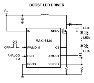
Figure 1. Common boost configuration for an HB LED driver.
To provide sufficient gate-drive voltage to the switching MOSFETs, the MAX16834 requires an operating voltage of at least 4.5V to bring the FETs into good conduction. This is not an uncommon requirement for an HB LED driver operating in a boost mode using n-channel FETs.
A power supply derived from a single Li+ cell could be as low as 3V, so the drive to the FETs and other supplies in the circuit would be insufficient for proper operation. Therefore, if the battery supply voltage could be boosted to a higher value, the device can operate correctly.
Boosting the battery supply once for the controller and then again for correct current control to the LED string has serious, negative consequences for power consumption and, therefore, battery life. This is because the overall efficiency is the product of the efficiencies of each stage. Or restated more precisely, 70% efficiency to boost followed by 70% efficiency in control would only give ~50% efficiency overall.
The solution described here uses a low-cost, low-power boost converter to provide a constant 5V supply to the HB LED driver in the EV kit. Meanwhile, the raw battery power is supplied directly to the FET boost converter stage. This way the battery power is boosted only once to power the LED string.
Boost Converter Powers LED String and FET Simultaneously
The MAX16834 is a highly versatile HB LED driver that offers dimming by both analog and pulse-width-modulation (PWM) control. It operates in boost, buck-boost, SEPIC, and high-side buck topologies. In addition to driving an n-channel power MOSFET switch controlled by the switching controller, it also drives an n-channel PWM dimming switch to achieve LED PWM dimming. It integrates all the building blocks necessary to implement a fixed-frequency HB LED driver with wide-range dimming control.
Some modifications to the MAX16834EVKIT were necessary. The MAX8815A boost converter was used in this design. Its EV kit is set to provide a 5V output by default, so there was no need for modification from the standard circuit (Figure 2).
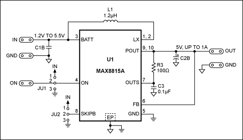
Figure 2. The MAX8815AEVKIT provides a 5V output needed for the application, so the circuit was not modified.
Solution Setup
The whole circuit was used to drive currents up to 1A into a series string of 6 Seoul Semiconductor P7 LEDs. While the LEDs are capable of much higher currents than those used in this example, the standard MAX16834 EV kit drives up to 1A which was sufficient for this analysis. Figure 3 shows the configuration for the HB LED driver and the boost converter.
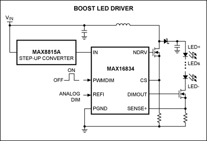
Figure 3. MAX16834 HB LED driver and the MAX8815A boost converter.
To eliminate the effects of voltage change or impedance increase during battery discharge, a high-current, low-voltage power supply was used instead of the battery. This kept the input voltage near constant as the current drive to the LEDs was changed to vary the system load.
The input and output currents and voltages were measured to provide data on the performance of the system at a 5V, 4V, and 3V supply which simulated the range of voltages expected with a single Li+ cell. Measuring the input and output currents would require separate calibrated digital voltmeters (DVMs), but there was an alternative approach. The input current was measured using the EV kit for a MAX9938 current-sense amplifier with a very low ohmic-value shunt to minimize measurement errors due to the shunt. The standard shunt is a 50mΩ, 4-terminal resistor, but this was bypassed with six 100mΩ resistors to give a 12.5mΩ shunt (Figure 4).
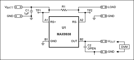
Figure 4. The MAX9938EV standard shunt is a 50mΩ, 4-terminal resistor (R1). R1 was bypassed with six 100mΩ resistors to give a 12.5mΩ shunt.
The transfer ratio, therefore, for the EV kit went from 2.5V per amp to 625mV per amp. Now the voltage output could be measured with the same DVM used for all measurements throughout the analysis.
The output current was determined by measuring the voltage across the 0.1Ω series resistor on the output of the EV kit using the same digital volt meter (DVM). This approach ensured that all current and voltage readings were made by measurement of voltage alone. Use of the same DVM for all measurements essentially nullified any calibration errors in the test gear. The system is shown in Figure 5.

Figure 5. System block diagram.
The results of the voltage measurements taken were entered into an Excel® spreadsheet to calculate the input/output currents and the input/output voltage measurements. Graphs of system efficiency for the three supply voltages were drawn (Table 1 and Figure 6).
| Measurements at 5V (nom) | |||||||||
| VIN | 4.98 | 4.97 | 4.94 | 4.93 | 4.91 | 4.89 | 4.86 | 4.83 | 4.81 |
| VOUT | 4.91 | 16.27 | 16.7 | 16.89 | 16.98 | 16.98 | 17.01 | 17.85 | 17.99 |
| Current in (A) | 0.04 | 0.50 | 1.03 | 1.47 | 1.97 | 2.44 | 3.05 | 3.36 | 3.79 |
| Current out (A) | 0 | 0.13 | 0.28 | 0.41 | 0.54 | 0.67 | 0.82 | 0.86 | 0.95 |
| Power in (W) | 0.17 | 2.50 | 5.07 | 7.24 | 9.67 | 11.93 | 14.82 | 16.23 | 18.24 |
| Power out (W) | 0 | 2.18 | 4.71 | 6.91 | 9.24 | 11.33 | 13.91 | 15.42 | 17.13 |
| Efficiency (%) | 0 | 87.04 | 92.81 | 95.40 | 95.52 | 94.92 | 93.88 | 95.03 | 93.90 |
| Measurements at 4V (nom) | |||||||||
| VIN | 4.02 | 4 | 3.97 | 3.96 | 3.94 | 3.92 | 3.89 | 3.88 | 3.85 |
| VOUT | 3.95 | 16.1 | 16.65 | 16.89 | 17.14 | 17.36 | 17.56 | 17.74 | 17.88 |
| Current in (A) | 0.03 | 0.50 | 1.08 | 1.45 | 1.91 | 2.44 | 3.21 | 3.38 | 4.08 |
| Current out (A) | 0.00 | 0.11 | 0.24 | 0.32 | 0.42 | 0.52 | 0.66 | 0.69 | 0.80 |
| Power in (W) | 0.13 | 1.98 | 4.27 | 5.75 | 7.53 | 9.55 | 12.50 | 13.10 | 15.71 |
| Power out (W) | 0.00 | 1.74 | 4.01 | 5.47 | 7.22 | 9.10 | 11.59 | 12.15 | 14.32 |
| Efficiency (%) | 0.00 | 87.64 | 94.01 | 95.12 | 95.79 | 95.29 | 92.73 | 92.77 | 91.18 |
| Measurements at 3V (nom) | |||||||||
| VIN | 3.01 | 2.99 | 2.976 | 2.957 | 2.94 | 2.924 | 2.885 | 2.867 | |
| VOUT | 2.95 | 16.07 | 16.45 | 16.73 | 16.86 | 17.11 | 17.37 | 17.45 | |
| Current in (A) | 0.03 | 0.56 | 1.02 | 1.52 | 1.96 | 2.40 | 3.46 | 3.88 | |
| Current out (A) | 0.00 | 0.09 | 0.17 | 0.25 | 0.31 | 0.38 | 0.51 | 0.57 | |
| Power in (W) | 0.10 | 1.66 | 3.02 | 4.49 | 5.77 | 7.02 | 9.98 | 11.11 | |
| Power out (W) | 0.00 | 1.43 | 2.75 | 4.22 | 5.28 | 6.42 | 8.84 | 9.86 | |
| Efficiency (%) | 0.00 | 85.91 | 90.86 | 93.80 | 91.50 | 91.37 | 88.55 | 88.70 | |
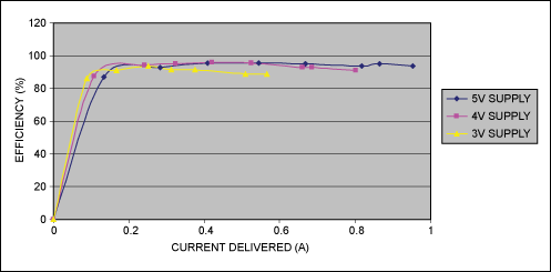
Figure 6. Performance data for the MAX16834 HB LED driver with three voltage supplies.
The measurements were taken with loads increasing from zero (all LEDs extinguished) to full load capability of the EV kit (up to approximately 1A on the LED string). The data shows that at lower voltages the power delivered to the output was reduced. This was because the input current to the system was limited to about 4A by the input power supply. This sort of limit might be typical of a battery source as well.
Conclusion
With a few minor modifications to the circuit, the challenges of driving a string of HB LEDs are met with the MAX16834. The overall power conversion efficiency was maintained around or above 90% even with battery supplies as low as 3V. Engineers can now use the latest technology, high-capacity Li+ cells to provide lighting for applications that used to require multiple stages of power conversion that, by itself, provided poor system efficiency and reduced battery life.
Related to this Article
Products
PRODUCTION
1A, 97% Efficiency, 30µA Quiescent Current, Step-Up Converter with True Shutdown
PRODUCTION
High-Power LED Driver with Integrated High-Side LED Current Sense and PWM Dimming MOSFET Driver
PRODUCTION
nanoPower, 4-Bump UCSP/SOT23, Precision Current-Sense Amplifier


