Abstract
Many of Maxim's battery monitors contain the option to include an internal sense resistor to measure current. This application note addresses any concern that self-heating generated by the flow of current through the sense resistor can introduce inaccuracies in on-chip temperature measurements. Data taken to determine the amount of self-heating introduced by the internal sense resistor is presented for the case of a standalone device and the case of a device coupled thermally to a battery cell. Additionally, in instances where the self-heating effects cannot be tolerated, correction calculations are presented which can be easily implemented in software.
Maxim's battery management devices have the option to integrate the sense resistor into the package. While this feature reduces cost and board size, concern may arise that heat generated by the integrated sense resistor can cause the on-chip temperature sensing to be inaccurate. On the contrary, the following application note shows that the heat generated is not significant enough to be a concern for most applications. For those applications that may be affected, a software solution to remove the effects is presented.
Self-Heating
The following data shows how power dissipation through the internal sense resistor heats the die and affects the accuracy of the on-chip temperature conversions. Dallas Semiconductor battery management products are designed to allow a maximum sustained sense resistor current of 2 amps. Therefore up to 2.0A2 × 30mΩ or 120 milliwatts of power could be dissipated by the device package during operation.

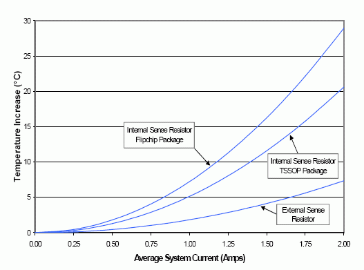
Figure 1a: Sense Resistor Self Heating without Coupling.

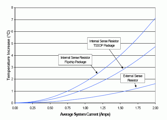
Figure 1b: Sense Resistor Self Heating when Coupled to Cell.
Figure 1a shows the effects of self-heating on a stand-alone package while Figure 1b shows the improvement when the package is thermally coupled to the cell. To gather the data, a flip chip DS2760 with internal sense resistor was compared to a TSSOP package DS2760 with internal sense resistor. For reference, a TSSOP DS2760 with an external resistor was also included. To more accurately simulate an enclosed battery pack, each device was enclosed in a container to prevent air from flowing over the package. The ambient temperature reading of each device was recorded with zero current flowing through the sense resistor. Current was then increased in steps of 0.25 amps up to a maximum of 2.0 amps. At each step, the device's temperature was allowed to settle and then an average of readings was taken from the temperature register. The entire process was repeated for Figure 1b with a Lithium Ion 18650 size cell thermally coupled to the device package with heat-sink compound.
The results from the non-thermally coupled devices show that the flipchip and the TSSOP experience an increase in die temperature of 30°C and 20°C (respectively) under worse case conditions. It is important to note that the severity is far beyond that found in most handheld applications. For example, GSM cell phone currents average only 300 to 400 milliamps and in these situations the temperature increase will be no greater than a few degrees Celcius. When thermally coupled to a battery, self-heating was reduced significantly. Typical temperature increases were roughly 75% lower than the non-coupled devices. Note that even the external resistor device experienced some heating through the board traces connecting the sense resistor to the IC. For reference, the external resistor was mounted 335 mils away from the DS2760 TSSOP with trace lengths of 650 mils.

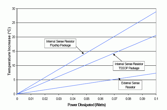
Figure 2: Sense Resistor Self Heating based on Power Dissipation.
Software Correction
If accurate temperature measurements are required, the effects of self-heating can be easily removed through some simple calculations performed by the system host. Figure 2 contains the same data as Figure 1a, except the die temperature increase is now compared against the power dissipated through the sense resistor. This linear relationship between heating and power can represented by the following equation allowing a simple implementation of software error removal:

Where:
TA = Actual Temperature
TM = Measured Temperature
I = Measured Average Current
R = Sense Resistance
n = Scaling Factor
The scaling factor used may vary greatly depending on application specifics such as package type, airflow, thermal coupling, etc. Its value for a given application can be easily determined through experimentation and stored in device EEPROM.
Summary
The effects of die self-heating for Dallas Semiconductor's internal sense resistor devices are minimal in most applications. Self-heating can be reduced greatly if the package is thermally coupled to the cell, which is recommended anyway, to allow more accurate reporting of the cell's temperature. Self-heating can be corrected in software for applications where very accurate temperature measurements are required.
Related to this Article
Products
High-Precision Li+ Battery Monitor
High-Precision Li+ Battery Monitor with Alerts


