Real Power Density: 26A μModule Regulator Keeps Cool in Tight Spaces
Real Power Density: 26A μModule Regulator Keeps Cool in Tight Spaces
Oct 1 2012
Each generation of high end processors, FPGAs and ASICs demands more power, but even as power supplies are expected to carry significantly heavier loads, they are given less board space to do so. It is now common for POL (point-of-load) supplies to produce multiple voltage rails at tens of amps to over a hundred amps at low, ≤1V, output voltages, and in less space than the generation before.
Supplies that must support high load currents and fit in tight spaces are often judged primarily on their power density, or watts/cm2. Indeed, many of the latest packaged power supplies and discrete solutions proclaim impressively high power densities—power supply manufacturers seem to be able to squeeze more and more power from smaller packages. Unfortunately, there is a big problem lurking behind amazing increases in power density. That problem is heat. (See "The Real Cost of Power Density" below.)
Heat dissipation is a significant problem at high currents and low voltages. In many systems, cranking up the power density actually compounds the problem, because more power in less space also pumps up the density of power losses—more heat in less space. It is not enough to simply squeeze a high power supply onto a board—the solution must also be carefully evaluated with regard to power loss and thermal resistance—two parameters that can make or break an otherwise good regulator. Claims of high power density can be impressive, but the promises made by these claims are empty if the heat produced by the supply is not effectively managed.
The LTM4620 solves the real power density problem by squeezing a complete dual output regulator into a 15mm × 15mm × 4.41mm LGA package that is uniquely designed to minimize thermal resistance and thus simplify thermal management. The package includes an internal heat sink and other cutting edge features that yield effective top and bottom heat sinking, allowing it to run at maximum load currents, even in elevated temperature environments.

The LTM4620 μModule® regulator enables high current power supplies to fit tight spaces. Thermal management is built into the package to prevent hot spots on the board, a common problem with POL power supplies.
Figure 1 shows the LTM4620 15mm × 15mm × 4.41mm LGA package. A single device can deliver two independent outputs at 13A (Figure 4) or a single output at 26A (Figure 5). Multiple LTM4620s can be combined to produce from 50A to more than 100A (Figure 7).

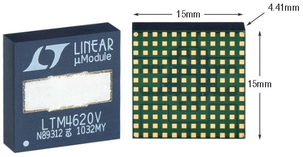
Figure 1. The LTM4620 LGA package includes thermal contacts on the top and bottom that connect to a unique internal heat sink, which keeps internal components cool by minimizing the internal thermal resistance.
The Real Cost of Power Density
Pay Attention to the Heat
Unwanted heat is a major challenge facing designers of high performance electronics systems. Modern processors, FPGAs, and custom ASICs dissipate increasing amounts of power as their temperature increases. To compensate for these power losses, power supplies must increase their power output. This, in turn, increases the power dissipation of the power supplies, contributing additional heat to an already hot system, and so on. Unless the heat is evacuated fast enough, the temperature of the entire system can elevate to the point where most components must be derated to compensate.
System and thermal engineers expend significant time and energy modeling and evaluating complex electronic systems to remove unwanted heat from the system. Fans, cold plates, heat sinks and even cooling bath submersion are all strategies that engineers have implemented to overcome the heat. Cooling size, weight, maintenance and cost become a significant portion of the engineering and manufacturing budget.
As systems add features and performance, the heat can only rise. Most processors and power supplies run about as efficiently as they can, and cooling systems are expensive mitigation. So simplification and cost savings must be found by improving power dissipation at the component level. The problem is that most compact packaged power solutions either dissipate too much power or their thermal resistance is too high—there is no way to effectively remove enough heat to operate them at elevated temperature without significant derating.
Power Density Numbers Not as Impressive as they Appear
The term high power density DC/DC regulator is misleading because it does not address the behavior of the device with respect to temperature. System designers often look to satisfy a watts/cm2 requirement, and power supply manufacturers are happy to oblige with impressive power density numbers. Even so, hidden in any device’s data sheet are temperature-related values that can be more important than the quoted power density.
For example, consider a 2cm × 1cm DC/DC regulator that delivers 54W to a load. This calculates to an impressive rated power density of 27W/cm2. This number should satisfy the power and size requirements of some designers. What’s often forgotten, though, is power dissipation, which translates into rising board temperature. The key piece of information is listed in the data sheet as the DC/DC regulator’s thermal impedance, including the values for the package’s junction-to-case, junction-to-air and junction-to-PCB thermal impedances.
To continue with this example, this regulator has another attractive attribute: it operates at an impressive efficiency of 90%. Even at such high efficiency, it dissipates 6W while delivering 54W to the output in a package with 20ºC/W junction-to-air thermal impedance. Multiply 6W by 20ºC/W and the result is a 120ºC rise above the ambient temperature. At a 45ºC ambient temperature, the junction temperature of the package of this DC/DC regulator rises to 165ºC. This is far above the typical maximum temperature specified for most silicon ICs, which is roughly 120ºC. Using this power supply at its maximum rating would require extensive cooling to keep the junction temperature at a value below 120ºC.
Even if a DC/DC regulator addresses all of the electrical and power requirements of the system, if it fails to meet the basic thermal guidelines, or proves too costly when heat-mitigation measures are taken into account, all the impressive electrical specifications are moot. Evaluating the thermal performance of a DC/DC regulator can be as important as judging it on volts, amps and centimeters.
Unique Package Design Achieves True High Power Density
The LTM4620 is designed from the ground up to produce dual or single outputs at high power density with easy-to-manage thermal characteristics. Unlike other high power density solutions, it is truly self-contained, requiring no unwieldy heat sinks or liquid cooling to run at maximum load current.
Figure 2 shows a side view rendering and a top view photo of an unmolded LTM4620. The package consists of a highly thermal conductive BT substrate with adequate copper layers for current carrying capacity and low thermal resistance to the system board. The internal power MOSFETs are stacked in a proprietary lead frame to produce high power density, low interconnect resistance, and high thermal conductivity to both the top and bottom of the device. Everything is topped off with a proprietary internal heat sink that attaches directly to the power MOSFET stacks and the power inductors for effective topside heat sinking.

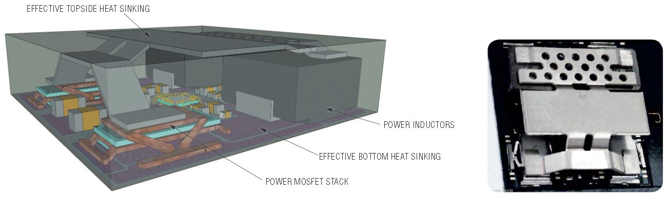
Figure 2. LTM4620 side view rendering and photo of an unmolded LTM4620 showing topside heat sink.
The construction of the heat sink and the mold encapsulation keeps the part running cool even when thermal management is simply forced air flow across the top of the package. For a more robust solution, an external heat sink can be attached to the topside exposed metal for even better thermal management.
Figure 3 shows a LTM4620 thermal image and a derating curve for a 12V to 1V at 26A design. The temperature rise is only 35°C above ambient with no heat sink and 200LFM of airflow. The derating curve shows that maximum load is available out to ~80°C, well beyond the 65°C that the thermal image shows for the full-running part.

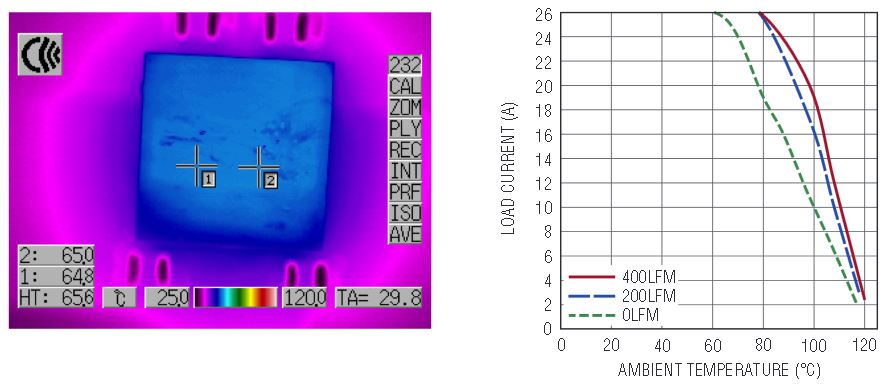
Figure 3. LTM4620 thermal image and derating curve.
This result reveals the real merits of a thermally enhanced high density power regulator solution. The unique package design allows the part to not only produce high power in tight spots, but it can do so without contributing significantly to the heat problem or requiring derating. Few, if any other high power density solutions can make this claim without adding expensive heat-mitigating components and strategies.
Dual 13A Regulator
Figure 4 shows a simplified block diagram of the LTM4620 μModule regulator in a dual output design. Its two internal high performance synchronous buck regulators produce 1.2V and 1.5V rails, each with 13A load current capability. The input voltage range is 4.5V to 16V.

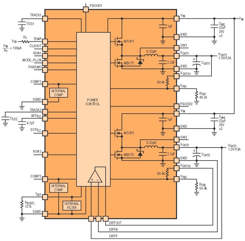
Figure 4. Block diagram of the LTM4620 in a dual output, 1.5V/13A and 1.2V/13A, application.
The output voltage range of the LTM4620 is 0.6V to 2.5V, and 0.6V to 5.5V for the LTM4620A. Total output accuracy is ±1.5%, with 100% factory-tested accurate current sharing, fast transient response, multiphase parallel operation with self-clocking and programmable phase shift, frequency synchronization, and an accurate remote sense amplifier. Protection features include output overvoltage protection feedback referred, foldback overcurrent protection, and internal temperature diode monitoring.
1.5V at 26A in 15mm2 with Easy Thermal Management
Figure 5 shows a 1.5V at 26A solution that combines the LTM4620’s two output channels in a parallel 2-phase design. The RUN, TRACK, COMP, VFB, PGOOD and VOUT pins are tied together to implement parallel operation. This design also features a LTC2997 temperature sensor that monitors the LTM4620’s internal temperature diode.


Figure 5. The two outputs of the LTM4620 can be tied together to produce a 2-phase, 2-parallel-channel, design that yields 1.5V at 26A. Internal diode temperature monitoring is provided through the LTC2997.
Figure 6 shows the 1.5V efficiency for the 2-phase parallel output and the current sharing of the two channels. 86% efficiency is very good for such a high density, high step-down ratio solution, and thermal results are as good or better than the 1V solution shown in Figure 3. The temperature rise is well controlled due to the low θJA thermal resistance after board mount. Effective top and bottom heat sinking enables the LTM4620 to operate at full power with low temperature rise.

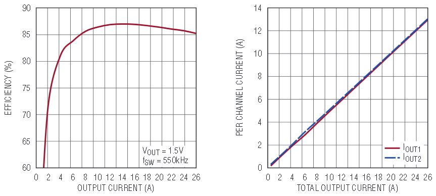
Figure 6. Efficiency and current sharing of 2-phase, single output 26A design shown in Figure 5.
Figure 6 shows the well-balanced current sharing of VOUT1 and VOUT2. The LTM4620’s internal controller is accurately trimmed and tested for output current sharing.
The LTM4620’s current mode architecture yields high efficiency and fast transient response—top requirements for low voltage core power supplies for high performance processors, FPGAs and custom ASICS. Outstanding initial output voltage accuracy and the differential remote sensing result in accurate DC voltage regulation at the load point.
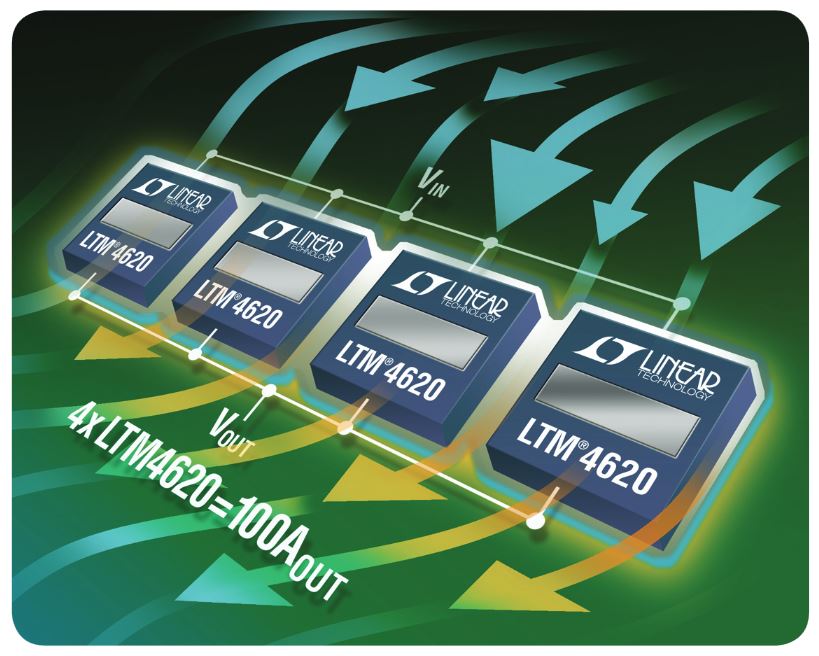
The unique thermal capabilities of the LTM4620 and its tight current sharing capabilities make it possible to easily scale the output above 100A (see Figure 7). No external clock sources are needed to set up multiphase operation—the CLKIN and CLKOUT pins produce internal programmable phase shifting for paralleled channels. The LTM4620 supports either external frequency synchronization or internal onboard clocking.

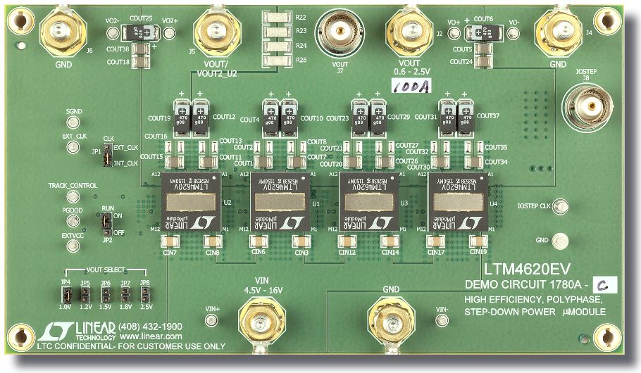
Figure 7. Four μModule regulators combined in an 8-phase parallel design support 100A.
Real Power Density: 100A in under 50mm2 with Air Cooling
Figure 7 shows four μModule regulators combined in parallel to produce an 8-phase, 100A design. Figure 8 shows the balanced current sharing for all four regulators. As shown in Figure 7 the entire 100A solution only takes about 1.95 square inches of board space. Even at this high current, a simple heat sink and air flow can be applied across the top of all four modules to remove enough power loss to require no derating. Releasing heat out of the topside also helps keep the system board cool to minimize the heating effect on other components.

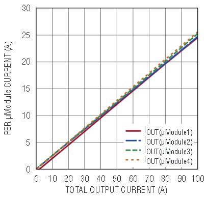
Figure 8. Current sharing for the four LTM4620s combined in a 100A design shown in Figure 7.
Conclusion
The LTM4620 μModule regulator is a true high density power solution. It differentiates itself in a the field of high power density regulators because it manages heat, the fatal flaw for many proclaimed high density solutions. It features two high performance regulators housed inside a superior thermal package, which makes possible high power designs that fit into tight spaces—with minimal external cooling. Built-in multiphase clocking and factory-tested accurate current sharing allow easy scaling of the output current to 25A, 50A, and 100A+. The LTM4620’s unique thermal properties allow full power operation at elevated ambient temperatures.
About the Authors
Eddie Beville is a power module design manager responsible for the design and development of the μModule® family. Eddie holds a BS in Electronic Engineering Technology from Chapman University, Orange, California. Eddie enj...
Related to this Article
{{modalTitle}}
{{modalDescription}}
{{dropdownTitle}}
- {{defaultSelectedText}} {{#each projectNames}}
- {{name}} {{/each}} {{#if newProjectText}}
-
 {{newProjectText}}
{{/if}}
{{newProjectText}}
{{/if}}
{{newProjectTitle}}
{{projectNameErrorText}}
Latest Media 21


