Abstract
This design note shows how a step-up DC-DC controller can be used in a negative buck-regulator application. With an external op amp to invert its voltage feedback, this boost-mode DC-DC controller derives a regulated −3V from the −5.2V ECL supply. The MAX1771 step-up DC-DC controller is featured.
A related idea appeared in the November 9, 1995 issue of EDN.
The circuit of Figure 1 adopts a step-up (boost) DC-DC controller for use in a negative buck-regulator application. It was developed to power the laser diode in an optical amplifier/booster unit, a job for which no commercial IC was available at the time. The anode of the laser diode connects to ground, so the supply voltage must be negative, and it must deliver 160mA to 750mA.
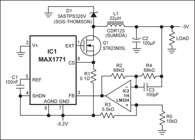
Figure 1. With an external op amp to invert its voltage feedback, this boost-mode DC-DC controller derives a regulated −3V from the −5.2V ECL supply.
Although the boost-regulator IC operates in a buck-regulator circuit, its standard connections enable proper control of Q1. The output voltage, however, must be inverted by an op amp for proper voltage feedback: the load is referred to the most positive supply rail instead of IC1's ground terminal, so the controller must increase its duty cycle as VOUT (referred to that terminal) increases. The op amp therefore inverts the feedback signal and shifts it to match the 1.5V threshold internal to IC1.
IC1 is configured in its non-bootstrapped mode, which provides an adequate gate-drive signal (ground to -5.2V) for the external MOSFET Q1. With VOUT set to -3V and the output current ranging from 160mA to above 700mA, the circuit's conversion efficiency ranges from 84% to as high as 87.5% (Figure 2).
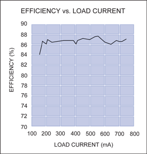
Figure 2. Efficiency for the Figure 1 circuit ranges from 84% to as high as 87.5%.
Related to this Article
Product Categories
Latest Media 21


