Abstract
This application note describes how to measure and improve the return loss (RL) on the Analog Devices DS3150 line interface unit (LIU). In this application note, the definition, requirements, measurement, and improvement of return loss are discussed.
Return-Loss Definition
When a high-speed signal reaches the end of a transmission line, if the transmission line is imperfectly terminated, a portion of the signal energy is reflected back toward the transmitter. This reflected signal mixes with the original signal, distorting that original signal and making it more difficult for the LIU receiver to correctly recover clock and data.
Return loss is the ratio (expressed in dB) of the power of the original signal vs. the power of the reflected signal. Thus, return loss indicates the relative size of the reflected signal and, therefore, how perfectly or imperfectly the transmission line is terminated. If the measured return loss of an LIU card is 20dB at a given frequency then the reflected signal has 20dB less power than the original signal at that same frequency.
Return-Loss Requirements
For E3, ITU G.703, and ETS 300-686, the input return-loss requirements are shown in Table 1, and the output return-loss requirements in Table 2.
| Frequency Range | Return Loss |
| 860kHz to 1720kHz | 12dB |
| 1720kHz to 34368kHz | 18dB |
| 34368kHz to 51550kHz | 14dB |
| Frequency Range | Return Loss |
| 860kHz to 1720kHz | 6dB |
| 1720kHz to 51550kHz | 8dB |
Measuring Return Loss on Analog Devices LIUs
The test setups and procedures for measuring E3 return loss are described in subclauses A.2.5 and A.2.6 of the ETS 300-686 specification. The test configuration in Figure 1 is designed to measure the input return loss and verify compliance with the requirements shown in Table 1. The output return-loss configuration is similar, with the same equipment connected to the transmitter output instead of the receiver input.
Figure 1. Return-loss measurement setup.
In the Figure 1 setup, the return-loss bridge is A57TLSTD from Wide Band Engineering Company, Inc.. Two 50Ω/75Ω impedance converters (A65L from Wide Band Engineering) are used to interface the 75Ω bridge with the 50Ω generator and 50Ω spectrum analyzer ports. The precision 75Ω resistor to the right of the bridge in Figure 1 is built into the return-loss bridge. An Advantest R3132 spectrum analyzer serves as both the signal generator and the spectrum analyzer.
In the Figure 1 setup, the generator is supplying a sinusoidal 1V-peak signal at frequencies ranging from 860kHz to 51550kHz.
To check the test setup before making return-loss measurements, the NTP interface of the bridge (the interface on the left in Figure 1) should be connected to a 75Ω ±0.25% test load. In the Figure 1 setup, this precision resistor is a component from Wide Band Engineering that comes with the return-loss bridge. With this test load, the return loss should be 20dB higher than the requirements shown in Table 1. Figure 2 shows the return loss measured with the Figure 1 setup using the 75Ω ±0.25% test load. The setup measured a 45.27dB return loss at 1720kHz.
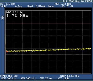
Figure 2. Return loss of 75Ω test load.
When the NTP interface of the bridge is connected to the receiver of the DS3150DK demo kit using a standard 330Ω termination resistor, the measured return loss is 15.27dB at 1720kHz, as shown in Figure 3. This value does not meet the requirements of Table 1. The next section describes how to improve return loss to meet those requirements.

Figure 3. Return loss of DS3150DK.
Improving Return Loss for the DS3150
Return Loss for the DS3150 LIU can be improved several ways.
- Change the termination resistor value from 330Ω to 390Ω.
- Replace PE-65968 transformers with a T3002 transformer and add a 100nH inductor in series with the primary coil.
Improving Return Loss for the DS3150 by Changing the Termination Resistor from 330Ω to 390Ω
The standard termination network for the DS3150 receiver is shown in Figure 4. Because it is difficult to create PC board traces with exactly the right characteristic impedance, it is often necessary to adjust the termination resistor value from the ideal 330Ω to improve return loss.

Figure 4. The original termination network for DS3150DK.
In the case of the DS3150DK board, replacing the 330Ω termination resistor with a 390W resistor significantly increases return loss. The return loss for the DS3150DK with the 390Ω termination resistor is 18.01dB at 1720kHz (Figure 5) and 23.39dB at 34.01MHz (Figure 6). Both of these values meet the requirements in Table 1.
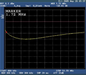
Figure 5. Return loss of the DS3150DK with modified termination network at 1720kHz.
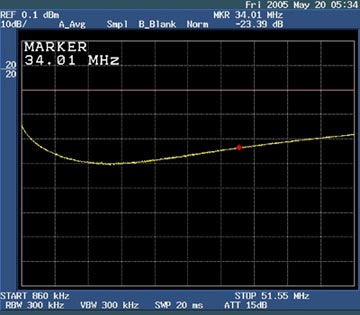
Figure 6. Return loss of the DS3150DK with modified termination network at 34.01MHz.
Improving Return Loss for the DS3150 by Changing the Transformer and by Adding a 100nH Inductor in Series with the Primary Coil
In this case, the following items were replaced on the DS3150DK board.
- Replaced PE-65968 transformers with T3002 transformer.
- Added a 100nH inductor in series with the primary coil.
The modified standard-termination network for the DS3150 receiver is shown in Figure 7.

Figure 7. The modified termination network for the DS3150DK.
Figure 8. Return loss of the DS3150DK with modified termination network at 1720kHz.
Figure 9. Return loss of the DS3150DK with modified termination network at 34.37MHz.
Conclusion
The return-loss measurement techniques and termination resistor adjustments described are also applicable for other Analog Devices DS3/E3/STS-1 LIUs and SCTs. The decision to modify the design to meet the return-loss specifications should be made after measuring the board with the ideal 330Ω termination resistor. If the return-loss requirements are not met with a 330Ω resistor, the termination resistor value can be adjusted or an inductor can be added in series with the primary coil.
If you have further questions on return loss or any other aspects of using Analog Devices telecom products, please contact the Tech Support team.
Related to this Article
Products
Single/Dual/Triple/Quad DS3/E3 Single-Chip Transceivers
Single/Dual/Triple/Quad ATM/Packet PHYs with Built-In LIU
Single/Dual/Triple/Quad DS3/E3/STS-1 LIUs
Single/Dual/Triple/Quad DS3/E3 Single-Chip Transceivers
3.3V DS21352 and 5V DS21552 T1 Single Chip Transceivers
Single/Dual/Triple/Quad DS3/E3/STS-1 LIUs
Single/Dual/Triple/Quad DS3/E3 Single-Chip Transceivers
3.3V, DS3/E3/STS-1 Line Interface Unit
3.3V DS21352 and 5V DS21552 T1 Single Chip Transceivers
DS3/E3 Single-Chip Transceiver
3.3V/5V E1 Single Chip Transceivers (SCT)
Single/Dual/Triple/Quad DS3/E3/STS-1 LIUs
T1/E1/J1 Single-Chip Transceiver
Single/Dual/Triple/Quad DS3/E3/STS-1 LIUs
Single/Dual/Triple/Quad ATM/Packet PHYs with Built-In LIU
Single/Dual/Triple/Quad DS3/E3/STS-1 LIUs
3.3V/5V E1 Single Chip Transceivers (SCT)
Single/Dual/Triple/Quad DS3/E3/STS-1 LIUs
Single/Dual/Triple/Quad ATM/Packet PHYs with Built-In LIU
Single/Dual/Triple/Quad DS3/E3 Single-Chip Transceivers
Single/Dual/Triple/Quad DS3/E3/STS-1 LIUs
Single/Dual/Triple/Quad ATM/Packet PHYs with Built-In LIU
Single/Dual/Triple/Quad DS3/E3/STS-1 LIUs
DS3/E3 Single-Chip Transceiver
Latest Media 21


