Individual LED Intensity Control with MAX6958/MAX6959 LED Drivers
Abstract
This application note details how to achieve pixel-level (individual LED) intensity control with the MAX6958 and MAX6959 LED display drivers. The technique augments the 64-step global (all LEDs at once) intensity control that is built into the drivers.
Introduction
The MAX6958 and MAX6959 LED display drivers use PWM 6-bit (64-step) intensity control to adjust the average LED current for all the lit LEDs simultaneously.This application note discusses how to expand the MAX6958's or MAX6959's capabilities to obtain individual pixel-level (LED) control as well.
Multiplex LED Driver Connection for Average LED Current
The MAX6958 and MAX6959 are 4-digit, 9-segment LED drivers which use a reduced-pin-count, multiplexing scheme (Charlieplexing—for technical details, see application note 1880, "Charlieplexing - Reduced Pin-Count LED Display Multiplexing") to drive 36 segments using only 10 drive pins (Table 1). The pin connections from the MAX6958/MAX6959 to the LED digits are not the standard connection, as Table 1 shows. Pins 4 to 7 share duty as both common cathode and anode drivers, depending on the multiplex cycle.
| DIG0/SEG0 | DIG1/SEG1 | DIG2/SEG2 | DIG3/SEG3 | SEG 4 | SEG 5 | SEG 6 | SEG 7 | SEG 8 | SEG 9/IRQ | |
| LED Digit 0 | CC0 | SEG 0 | SEG g | SEG f | SEG e | SEG d | SEG c | SEG b | SEG a | SEG 4 |
| LED Digit 1 | SEG 1 | CC1 | SEG g | SEG f | SEG e | SEG d | SEG c | SEG b | SEG a | SEG 5 |
| LED Digit 2 | SEG g | SEG f | CC2 | SEG 2 | SEG e | SEG d | SEG c | SEG b | SEG a | SEG 6 |
| LED Digit 3 | SEG g | SEG f | SEG 3 | CC3 | SEG e | SEG d | SEG c | SEG b | SEG a | SEG 7 |
The MAX6958/MAX6959 operate a four-way multiplex driving, in turn, the cathodes of four groups of nine LEDs. The groups are called LED Digit 0, 1, 2, and 3. The four cathode connections for LED Digit 0 through 3 are CC0 through CC3 in Table 1, and the LED anode connections are prefixed SEG. During normal multiplexed operation, cathode outputs CC0 through CC3 go active low one at a time, enabling each digit sequentially for a quarter of the time.
A 6-bit (64-step) PWM global intensity control adjusts the average current (and therefore, the perceived brightness) of the LEDs. This works by adjusting the actual time that the cathode outputs CC0 through CC3 are switched on during their multiplex timeslots. The same PWM value is applied to cathode outputs CC0 through CC3, and there is no individual adjustment for each anode drive's constant current source. Consequently, all LEDs' intensities are adjusted equally.
Achieving Individual LED Intensities
Highlighting specific LEDs is useful in many applications. Blinking is one way to achieve this, and cursors often use blinking to highlight their position. Another good method for highlighting segments is to make them brighter than the other LEDs. This latter method is not possible using the standard MAX6958/MAX6959 multiplex configuration as described above.
A simple way to give LED segments individual intensity control is to allow them to be driven by more than one multiplex cycle, a dual drive. Figure 1 illustrates this with a single, 7-segment-plus-decimal-place digit driven in place of the usual 2-digit pair of LED Digit 0 and LED Digit 1. Note that Figure 1 is not complete. LED Digit 2 and LED Digit 3 are not shown; they could be another single digit, or two digits in the normal manner.

Figure 1. Wiring the MAX6958/MAX6959 to drive a digit with 2-step individual intensity control.
The dual-drive digit in Figure 1 is driven for two multiplex cycles instead of the normal one. In this case diodes D1 and D2 steer the two cathode drives so that when either CC0 or CC1 goes low as cathode drive, the same LEDs operate. Because the dual-drive digit is replacing two normal digits, it is controlled by two digit registers (Digit 0 and Digit 1,0x20 and 0x21, respectively) instead of just one digit register. Each LED is represented by two bits (one in each digit register) instead of one. If both bits are clear, then the LED will be off. If just one bit is set and the other is clear, then the LED will be on at normal brightness. If both bits are set, then the LED will be on at twice normal brightness. Each LED, therefore, has two intensity settings instead of one. LEDs wired normally, such as SEG0 and SEG1, can only be set to normal brightness. As the diodes D1 and D2 carry the 20mA current for eight LEDs for a quarter of the time each, so they must be rated for 160mA peak, 40mA average.
There is a trade-off with Figure 1. Here the MAX6958/MAX6959's digit-drive capability is reduced, because every LED provided with two intensity settings takes the drive capability of two 'normal' LEDs. The MAX6958/MAX6959 can only drive two 7-segment digits with two intensity settings per pixel, instead of four with standard on/off control. This technique can, however, still be used effectively and economically where just a few LEDs require intensity control. Figure 2 shows a single LED as dual-driven, at the sacrifice of the drive capacity of only a single LED. Here, the diode pair, D3, carries the 20mA current for only one LED, 20mA peak, and so can be a low-cost, signal dual-diode.
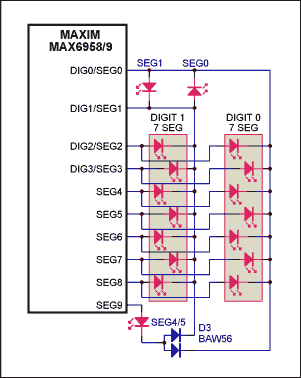
Figure 2. Wiring the MAX6958/MAX6959 to give just one LED 2-step individual intensity control.
Alternate Wiring Scheme for Individual LED Intensity
The back-to-back LEDs SEG0 and SEG1 can also be replaced by a single diode with 2-step intensity control. A diode bridge rectifies the back-to-back drive, as shown in Figure 3. Because two diodes are in series with the LED's current path in this case, the diodes are small-signal Schottky diodes to minimize the voltage drop.

Figure 3. Alternate wiring for the MAX6958/MAX6959 to give just one LED 2-step individual intensity control.
{{modalTitle}}
{{modalDescription}}
{{dropdownTitle}}
- {{defaultSelectedText}} {{#each projectNames}}
- {{name}} {{/each}} {{#if newProjectText}}
-
{{newProjectText}}
{{/if}}
{{newProjectTitle}}
{{projectNameErrorText}}


