Implement an Accurate and Rugged Motor Control Sensing System
Abstract
Driving motor system speed and torque correctly require feedback accuracy and signal integrity to respond to provide stability inside the motor's dynamic range. This design solution compares low-side, high-side, and in-line current sensing, with a final recommendation towards the in-line current sensing circuitry. The in-line is a robust current sensing circuitry that preserves the phase relationships of the three legs of the AC motor.
Introduction
Modern motor control systems require feedback accuracy and signal integrity to drive system responses such as speed and torque correctly and provide stability inside the motor’s dynamic range (Figure 1).

Figure 1. AC brushless three-phase motor.
When capturing motor information, there are three motor control measurement strategies: low-side or high-side, or in-line (also direct winding) current sensing (Figure 2).
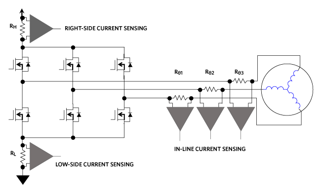
Figure 2. The low-side, high-side, and In-line circuit options, for motor speed and torque sensing.
This deisgn solution compares the three motor-control approaches and recommends the appropriate electronics for a robust current sensing circuitry.
Low-Side Motor Current Sensors
The low-cost, low-side current sensing application uses an amplifier and sense resistor (RL) at the bottom of the gate-driving FET stack. The low-side sensing system keeps the amplifier operation near ground and captures the ampere activity of each leg in succession.
As an advantage, the sense resistor (RL) and amplifier are close to ground, simplifying the circuit design. Additionally, a non-inverting amplifier input at the top of the sensing resistor presents limited interference with its high non-inverting terminal input-impedance.
As a disadvantage, the current sensing resistor, between ground the motor legs, adds an undesirable dynamic voltage drop and disrupts the ground path.. This added resistor, RL, produces an offset voltage that can cause EMI noise problems. If the load becomes shorted to ground, the RL resistance removes the ability to detect faults in the load. The combination of the sense resistor and amplifier capture motor fly-back and return currents. Unless a sense resistor and amplifier are used in each leg, the only way to calculate the winding currents is with the MCU algorithm.
High-Side Motor Current Sensors
The high-side resistor, directly connected to the FET driver positive supply source, minimizes the resistor’s dynamic AC voltage impact on the entire system. This configuration is less intrusive, generating minimal EMI characteristics. Additionally, a high common-mode-rejection-ratio (CMRR) differential amplifier filters pulse-width-modulator (PWM) switching noise.
The high-side approach requires that the circuity copes with large common-mode signals at the FET network supply voltage. This requirement necessitates a robust amplifier that handles potentially high voltages. Finally, the circuit position of RH makes fly-back and winding current measurements impossible.
In-Line Motor Current Sensors
The in-line (or direct winding) is the preferred approach because it provides the true, current phase information. In the direct winding configuration, the system processor knows the current in each phase of the three-phase motor at any given time, resulting in a more efficient motor operation (Figure 3).

Figure 3. In-line current sensing for motor control.
In Figure 3, all three legs are simultaneously sampled by the MCU to preserve the phase relationships between each leg excitation.
An ideal amplifier for in-line measurements amplifies each motor leg’s differential signal, with a rejection of the pulse-width-modulation (PWM) common-mode transients. Amplifiers with a fast settling time, high-bandwidth can reject common-mode transients. Strong PWM rejection facilitates the fastest settle time, higher accuracy, and enables the customer to minimize PWM duty-cycle as close to 0% as possible.
The solution to a rugged motor control system is to use an in-line, fast settling time, high-bandwidth amplifier that rejects common-mode transients.
The 300kHz MAX40056 is a bi-directional current-sense amplifier with high AC PWM edge 60dB rejection at 50V, ±500V/µs (Figure 4).

Figure 4. Current sense amplifier (CSA) patented PWM rejection circuitry.
In Figure 4, there are multiple gain options of 10V/V, 20V/V, and 50V/V. The internal reference has a 1% bidirectional offset.
This device has a 500ns PWM edge recovery from 500V/µs and higher PWM edges. The input common-mode voltage range is -0.1V to +65V and the amplifier is protected from -5V to +70V. The MAX40056 and competitor bench data illustrate a significant difference in the PWM common-mode immunity (Figure 5).

Figure 5. PWM edge rejection of a 50V PWM cycle.
In Figure 5, the MAX40056 CSA’s analog output shows a minor bump and recovers within 500ns while the competing device requires approximately 2µs to recover. CSA’s patented PWM rejection input suppresses transients and provides a clean differential signal measurement.
Conclusion
This design solution compares the three motor-control approaches: low-side, high-side, and in-line current sensing. The recommended motor current sensing approach is the in-line, which is a robust current sensing circuitry that preserves the phase relationships of the three legs of the AC motor.
A similar version of this design solution originally appeared in Electronic Products on August 07, 2020.
Related to this Article
Products
RECOMMENDED FOR NEW DESIGNS
Bidirectional Current Sense Amplifier with PWM-Rejection
PRODUCTION
Bidirectional Current Sense Amplifier with PWM-Rejection
PRODUCTION
Bidirectional Current Sense Amplifier with PWM-Rejection
Product Categories
Latest Media 21


