How to Best Test Wireless Systems? Timing and Synchronization
How to Best Test Wireless Systems? Timing and Synchronization
Jan 7 2022
Abstract
This article discusses in detail the important factors to be considered during wireless system testing, specifically system-level tests involving timing and synchronization, and it tackles how these are essential to wirelessly transmitting data between transmitter and receiver blocks within a certain margin of error. The factors discussed in this article will help develop test cases that will determine the functional and nonfunctional specifications, system boundaries, and bugs to ensure a highly reliable and synchronized wireless system.
Introduction
Rapid advancements in wireless technology opened a new era in wireless communications. It is used almost everywhere and has brought a significant impact on the advancements in the innovation of different areas like communication, healthcare, automotive, and space exploration industries. Its market is well established and is witnessing a period of dynamic growth. It is expected to expand its revenues from $1431.3 billion in 2019 to $5519.4 billion by 2024, at a CAGR of 31%. Wireless technology is still evolving and continues to open more possibilities by achieving higher accuracy, higher operational efficiency, quicker decision-making capability, higher data rates, and more cost savings. However, the increasing functionality of these devices also increases the complexity in the context of wireless system-level testing.
Accurate timing and synchronization are fundamental requirements for any wireless system to work properly. These are processes of matching both transmitter and receiver clocks in the system within identified tolerances. They ensure maximum packet integrity and optimized data flow, and they should always be highly considered in any wireless system testing and development. However, achieving these requirements is difficult since clock sources are notorious for their drift. Even a small drift in microseconds can accumulate over time and can cause a system to lose synchronization. Perfectly synchronized wireless systems can only be achieved when the clocks are perfectly matched. But realistically, this is very challenging. Drift is an inherent characteristic of clocks that can cause differences on the clocks’ counting time and can eventually result in desynchronization.
A system with poor synchronization can lead to degraded transmission that decreases the quality of the data being transmitted. Moreover, it can lead to loss of data integrity and can result in operations failure, which is very crucial in life and safety-critical applications that can impact the health, security, and safety of people. Causing a negative impact in these applications may lead to legal liabilities and loss of credibility to the customers.
Because of this considerable need for a well-synchronized system, multiple synchronization techniques are used depending on the requirements, such as precision and degree of mobility. These are:
Sender-receiver-based synchronization


Figure 1. Sender-receiver-based synchronization.
Receiver-receiver-based synchronization


Figure 2. Receiver-receiver-based synchronization.
Delay measurement synchronization


Figure 3. Delay measurement-based synchronization.
The sender-receiver-based synchronization is a two-way message exchange. One example of this is the timing-sync protocol for sensor networks (TPSN). In TPSN, network synchronization is done by transmitting and receiving synchronization pulse packets between nodes. The time offsets of each transfer are timestamped and calculated to determine the clock time difference, which is used to synchronize the nodes.
The SFD-based synchronization uses a one-way message exchange. Reference broadcast synchronization (RBS) uses this type of synchronization.
Delay measurement synchronization, like the receiver-receiver-based synchronization, is also a one-way message exchange; however, it measures delay. One example of this is delay measurement time synchronization (DMTS).
The succeeding sections will discuss in detail the different timing and synchronization parameters used in wireless systems that use the TPSN, how each parameter affects the overall functionality of the system, and how these parameters can be configured to ensure a more stable and synchronized system. Moreover, during wireless system-level testing, these parameters will help identify bugs and system boundaries related to timing and synchronization.
Timing and Synchronization Parameters
Sync Reference
The radio provides the ability for software to schedule transmit and receive commands accurately by using a sync reference point. Events are scheduled with a positive offset from the reference point to allow synchronization between the transmitter and the receiver. The following are the common reference points used in a wireless system:
Sync Now
The synchronization reference point is set at the time at which the sync command (set_sync_ref(NOW)) is processed.
Figure 4 shows a packet being transmitted with respect to the reference set by the (set_sync_ref(NOW)) command.


Figure 4. Sync now.
Sync SFD
The synchronization reference point is set at the start of frame (SOF), indicating that a valid sync word was detected.
Sending the command (set_sync_ref(SFD)) sets the reference point right after the first start of frame detect (SFD) after the command was sent. In Figure 5, the second transmit packet was transmitted with respect to the SFD reference point.


Figure 5. Sync SFD.
Sync Latest
In this sync mode, the synchronization reference point is set every SOF. As shown in Figure 6, for each subsequent valid packet sync word received, the synchronization reference is updated to the timestamp of the latest SOF.


Figure 6. Sync latest.
Using these sync modes enables synchronization between two nodes. However, it is important to take note that the hardware clock is known for its drift, which causes its frequency to vary over time and can lead to inaccuracies. As a result, the clocks will likely to be different at any given time. Updating the sync references of the transmit and receive clocks recurrently minimizes skew and the effects of drift.
Time Offset
Time offset is the time difference of the current time from the beginning of the time capture or sync reference. This parameter is used when transmitting or receiving.
The minimum time offset start is the minimum time needed for a transmit/ receive command to immediately execute. This parameter is calculated based on the inherent delay of the API and the radio. Values less than this can cause scheduling errors, leading to unsuccessful transmit/receive transactions.


Figure 7. Time offset.
Figure 8 shows a scenario where the time offset used is less than the minimum allowable time, which resulted in a command scheduled to a time that has already passed.


Figure 8. Scheduling a packet past the set offset.
When executing two successive transmit and receive commands (Tx-Tx or Rx-Rx), the size of the first packet is an important factor in determining the time offset that can be used to successfully execute the second command when both use a single time reference. As the length of the first packet increases, the time offset of the second command must also increase to ensure a successful transaction. Using a time offset less than the allowable minimum time offset will schedule the second packet while the first packet is still executing, thus causing a failure. This is shown in Figure 9.

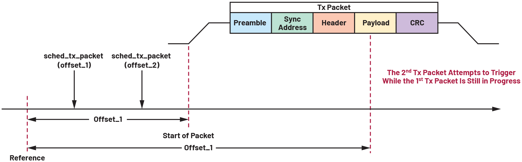
Figure 9. Packet scheduling using time offset.
Max Time Offset
Max time offset is used to prevent scheduling of packets outside the set time. Due to clock drifts, scheduling packets too far from the sync reference can cause inaccurate scheduling, which can cause signal detect timeout or SOF timeout. These timeouts will be discussed more in the timeout section.
Turnaround Time
The turnaround time is defined as the time required by the physical (PHY) layer to change from receive mode to transmit mode or vice versa. During turnaround time, the components in the analog RF front end are powered up and stabilized, which consumes a considerable amount of time. This time consumption becomes more critical for low latency feedback applications, such as process control loops in industrial systems where remote control of robotic arms or other machineries is involved. Turnaround time is only applicable on half-duplex transceivers.
Turnaround time is used when the user needs to send a transmit packet as soon as the PHY layer is ready again after a receive package (or vice versa).
Figure 10 shows two packets, receive and transmit. In this scenario, the command sched_rx_packet(0) causes the transceiver to prepare receiving a packet. In this example, the offset was set to 0, which means that the transceiver will immediately start receiving a packet once the PHY is ready. During packet reception, sched_tx_packet(0) command was sent causing the PHY layer to switch to turnaround state. The software schedules the transmit packet with receive done as the reference point then adds the turnaround time value.


Figure 10. Packet scheduling with turnaround time.
Figure 11 shows what happens when no turnaround time is set in the software. Since no turnaround value is set, the scheduler sets the next packet to transmit immediately after the first packet. The scheduler does not know that the PHY layer is not capable of transmitting/receiving yet since it still has to change its state, causing the next packet to fail.


Figure 11. Packet scheduling without turnaround time.
This shows the importance of setting the turnaround time. Without it, the user won’t know if a receive being scheduled during a transmit (or vice versa) will be successfully executed or not. The turnaround time value should be based on the duration the PHY layer could transition from the PHY transmit state to PHY receive state. This scenario is critical for cases where the RF devices frequently switch from transmit to receive or vice versa.
Interpacket Gap
Interpacket gap is the time counted from the last bit of the previous frame to the first bit of the subsequent frame (both over the air). Like turnaround time, interpacket gap is used as a reference in sending a packet while another packet is being transmitted/received. The difference is that interpacket gap is used between two packets of the same type (Tx-Tx or Rx-Rx). Interpacket gap is necessary for transceivers to prepare the PHY for the next packet.
Figure 12 shows two packets, transmit and transmit. In this scenario, the command sched_tx_packet(0) causes the transceiver to start transmitting a packet immediately. Sending another sched_tx_packet(0) command while the first packet is not yet done transmitting causes the scheduler to set the next packet to start transmitting as soon the current packet is done transmitting. The interpacket gap value is used by the scheduler as a reference when to transmit the next packet. Its value is based on the ramp-down and the ramp-up time of the PHY. This ensures that the PHY is ready to do another packet transmission/reception.


Figure 12. Packet scheduling with interpacket gap.
Figure 13 shows an error when no interpacket gap is set. The scheduler sets the next packet to transmit right after the first packet is done transmitting/receiving. However, the same with turnaround time, the scheduler does not know that the PHY is still not ready to do another transmission/reception.


Figure 13. Packet scheduling without interpacket gap.
Timeouts
In wireless systems, timeouts are used to prevent devices from infinitely waiting for a response. Timeouts are set with an allowable period for the device to wait for a valid response. If no valid response was received within the timeframe, an error will be reported. The most common types of timeouts are the following:
Start of Frame Timeout
SOF timeout occurs when an invalid sync is detected. SOF timeout can also occur when the SOF timer expires before receiving the sync word.
Figure 14 shows a valid sync address detected within the SOF timer period while Figure 15 shows a scenario where an SOF timeout occurs because no valid sync address was detected within the allotted time.


Figure 14. Packet detection with the correct sync address.


Figure 15. SOF timeout error due to an invalid sync address.
Signal Detect Timeout
Signal detect timeout occurs when no valid preamble is detected within the SD period or the timer expires before receiving the preamble. These are shown on Figures 16 and 17.


Figure 16. SD timeout error due to late packet.


Figure 17. SD timeout error due to no packet detected.
Figure 18 shows a scenario where a valid preamble is detected within the timer period; thus, no timeout was detected.


Figure 18. No SD timeout.
It is important to set an appropriate timeout period. Timeouts must not be too short or too long. Using timeouts that are too short will cause a spurious detection wherein there is a valid packet but there’s not enough time for it to be detected due to the short timeout. Using longer timeouts will decrease the number of spurious timeouts but will cause the device to stay in an active state for a longer time, which means more power consumed and wasted.
Conclusion
Time synchronization is an important element in wireless systems especially in applications where data integrity is a critical requirement. There are numerous factors that can affect the system’s synchronization and having a substantial knowledge on the relevance and the characteristics of its timing parameters will aid engineers in developing and executing wireless system-level test of highly reliable wireless systems.
About the Authors
Jeffrey Ryan F. Fajutagana is a firmware engineer in the Software Systems Engineering (SSE) group at Analog Devices in Philippines. He joined Analog Devices in 2018 after receiving his bachelor's degree of Electrical Engin...
Kiana V. Khey is a Firmware Engineer under the ADGT Software Systems Engineering (SSE) group. She graduated from the Technological University of the Philippines – Visayas in 2015 with a bachelor’s degree in Electronics Eng...
Related to this Article
{{modalTitle}}
{{modalDescription}}
{{dropdownTitle}}
- {{defaultSelectedText}} {{#each projectNames}}
- {{name}} {{/each}} {{#if newProjectText}}
-
 {{newProjectText}}
{{/if}}
{{newProjectText}}
{{/if}}
{{newProjectTitle}}
{{projectNameErrorText}}
Latest Media 21


