Guidelines for the Opto-Mechanical Integration of Heart-Rate Monitors in Wearable Earbud Devices
Abstract
The opto-mechanical integration of a heart-rate monitor in an earbud wearable is a fundamental step in designing a fitness tracking earbud device. The quality of the signal can be greatly affected by choosing designs that minimize crosstalk and maximize signal. This application note discusses the optical and mechanical aspects to consider for optimal performance. The optical design focuses on the interaction of light with the skin and blood. The mechanical design provides suggestions that increase coupling with the optics and skin.
Introduction
More people are tracking their physical fitness with the aid of wearable fitness armbands and smartwatches. These activity trackers use optical sensors to measure heart rate and other biometric values. This technology, established in wearable wrist applications, can now be transferred to wearable earbuds.
Maxim Integrated’s MAX86160 and MAXM86161 are integrated heart-rate sensor modules optimized for earbud applications. Both modules include internal LEDs, photodetector, IR sensor, and low-noise electronics with high-dynamic-range ambient light rejection. These products are a complete system solution and come with plug-and-play software and robust algorithms to give meaningful outputs to the user. While the modules take care of the LED, photodetector, and electronic module integration, the customer must decide how best to integrate the module into their earbud’s industrial design. This application note outlines how a reflective heart-rate monitor such as the MAX86160/MAXM86161 operate and provides practical recommendations on how to integrate Maxim’s heart-rate monitors into an earbud device.
Theory of Operation
Photoplethysmography (PPG) is the principle on which optical sensors measure heart rate. As the heart pumps, the volume of blood transported in the arteries changes. More blood flows through the arteries when the heart expels blood (systolic phase) and less blood flows when the heart draws blood (diastolic phase). When the blood volume changes between systolic and diastolic heart beats, it results in a change in the optical absorption coefficient of the arterial layer. By optically illuminating the tissue and measuring the transmitted light, the absorption change due to the blood volume change can be determined and the heart-rate pulsatile signal can be recovered.
On certain regions of the body such as the ear, transmissive heart-rate measurements are logistically difficult, so reflective measurements are used. Reflective heart-rate monitors consist of a light source and a detector arranged in the same plane (Figure 1). The light emitted penetrates the skin, tissue, and blood vessels and is either absorbed, scattered, or reflected back on the photodetector. Because the volume of blood in the arteries changes with every beat of the heart, the amount of light absorbed and the strength of the detector signal also change.
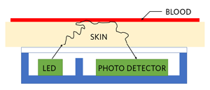
Figure 1. The principle of reflective optical-pulse measurements.
Interaction of Light with the Skin
The skin consists of three main layers from the surface: the blood-free epidermis layer (100µm thick), vascularized dermis layer (1mm to 2mm thick), and subcutaneous adipose tissue (1mm to 10mm thick depending on the body site). Typically, the optical properties of these layers are characterized by absorption (µa), scattering µs coefficients, and the anisotropy factor (g).
The absorption coefficient characterizes the average number of absorption events per unit path length of photons traveling in the tissue. The main absorbers in the visible spectral range are melanin, which is blood composed of oxyhemoglobin (Hb), deoxyhemoglobin (HbO2), and lipids. In the IR spectral range, the absorption of water dominates the absorption properties of the skin dermis.
Figure 2 is a planar seven-layer optical model of human skin. The layers included in this model are the following:
- Stratum corneum
- Two layers of living epidermis.
- The first layer contains the papillary dermis and superior blood net dermis
- The second layer contains the reticular dermis and inferior blood net dermis
- Subcutaneous adipose tissue
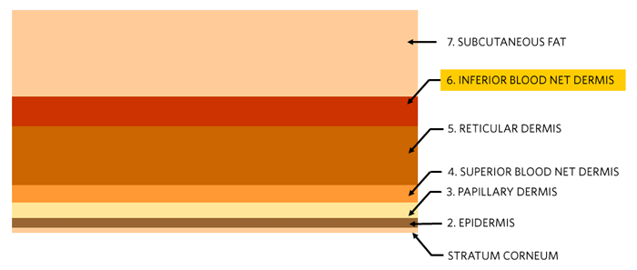
Figure 2. Seven-layer skin model. The first and outermost layer is the Stratum corneum and the innermost layer is the subcutaneous adipose tissue, or fat layer.
| Layer | tdickness | Volume Fraction | Refractive Index | |||
| t(µm) | θBlood | θWater | θMel | n | ||
| 1 | Stratum corneum | 20 | 0 | 0.05 | 0 | 1.40 |
| 2 | Epidermis | 80 | 0 | 0.2 | 0.01 – 0.10 | 1.40 |
| 3 | Papillary dermis | 150 | 0.0024 | 0.5 | 0 | 1.39 |
| 4 | Superior blood net dermis | 150 | 0.0060 | 0.6 | 0 | 1.39 |
| 5 | Reticular dermis | 1000 | 0.0024 | 0.7 | 0 | 1.41 |
| 6 | Inferior blood net dermis | 600 | 0.0120 | 0.7 | 0 | 1.41 |
| 7 | Subcutaneous fat | 8000 | 0.0012 | 0.7 | 0 | 1.44 |
The heart-rate pulsatile signal originates from the arterial bed that is lying down in the inferior blood net dermis layer, which is the sixth layer in the seven-layer tissue model in Table 1. The absorption spectrum of this layer can be calculated using the absorption spectra of tissue constituents and its corresponding volume fractions by using the following equation:
µa(λ) = (Sµa.Hb(λ) + (1 - S)µa.HbO2(λ))θblood + µa.mel(λ)θmel + µa.water(λ)θwater + µa.lip(λ)θlip
where µa.mel, θmel, µa.water, µwater, µa.lip, θlip are the absorption coefficients and volume fractions of melanin, water, and lipids, respectively. µa.hb and µa.HbO2 are the absorption coefficients of oxyhemoglobin and deoxyhemoglobin, and θblood is the volume fraction of blood. S is the blood oxygen saturation coefficient, typically around 95% in healthy individuals.
Use Equation 1 and the measured absorption spectra for the tissue constituents[1] to calculate the absorption coefficient in the inferior blood net dermis as a function of wavelength. Figure 3 plots the results.
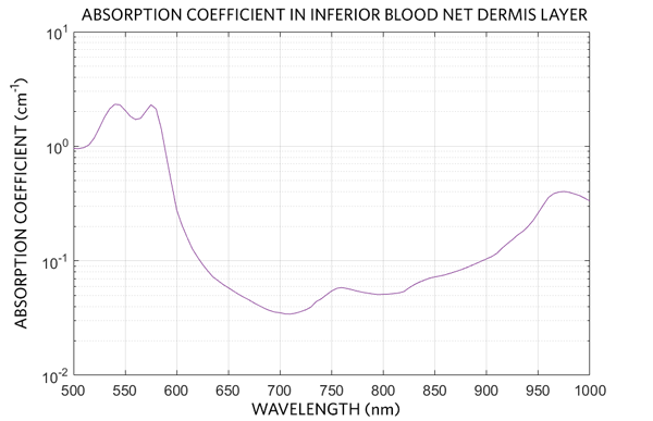
Figure 3. Absorption coefficient in the inferior blood net dermis layer as a function of wavelength.
Optomechanical Design Considerations
Designing a good PPG solution is very complex and is often underestimated. Fortunately, Maxim Integrated’s modules take care of the most challenging parts of the design by incorporating the light emitting elements, photodetector, and low-noise electronics into a single module under an attached cover glass. However, the heart-rate module still needs to be successfully incorporated into the earbud design from an opto-mechanical point of view to ensure a reliable and precise optical signal. Successful integration maximizes both the signal received by the sensor and the signal-to-noise. Maximize the signal-to-noise by maximizing the signal that has penetrated deep enough into the skin to create a PPG signal and minimizing crosstalk. Crosstalk is signal on the sensor from sources other than the PPG signal.
Figure 4 shows a typical opto-mechanical integration. The LED/sensor module lies beneath the customer’s industrial design. The industrial design consists of a transparent cover which serves as a moisture barrier and interface between the module and the ear. The Maxim modules provide an internal crosstalk barrier between the LEDs and photodetector, but customers can use additional external barriers to further suppress crosstalk. There are many methods to integrate crosstalk barriers and transparent covers into an earbud design.
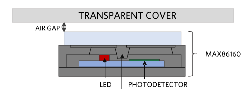
Figure 4. Typical opto-mechanical design.
Transparent Cover
Choose a material for the transparent cover that has a high transmission (greater than 90%) in the wavelengths utilized by the heart-rate monitor to maximize the light emitted into the skin and signal returning from the skin. To minimize transmission loss, the transparent cover should be as thin as possible while still providing the robustness to withstand normal wear and tear. Additionally, the transparent cover should have an index of refraction close to that of human skin (approximately 1.4) to minimize transmission losses due to Fresnel reflections.
Corning® Gorilla® Glass fits both these criteria. The index of refraction of Corning Gorilla Glass is 1.5, the transmission at the Maxim module’s operating wavelengths (532nm and 880nm) is over 91%, and the glass provides a structurally sound cover with a thickness as thin as 200µm. Other potential material candidates include acrylics and polycarbonates.
Another method of integrating the module into the industrial design is to encapsulate the module in a transparent material. A sealant provides waterproofing properties but also increases the signal received by the sensor. Minimize transmission losses due to Fresnel reflections by choosing a sealant that has an index of refraction close to that of human skin. Additionally, a sealant that provides some “give” increases the contact area and pressure with the skin. Silicones are commonly used sealants. Table 2 lists good silicone candidates and their characteristics to choose as an encapsulation material.
| Manufacturer | Product Name | Color | Viscosity (cP) |
Index of Refraction | Transmission (3.2mm tdick) |
Hardness | Comments |
| Dow Corning | Sylgard 184 Silicone Elastomer | Colorless | 3,500 | 1.4118 at 589nm 1.4225 at 632.8nm |
97% at 532nm 96% at 880nm |
Durometer Shore 43 | High transmission, flexible elastomer |
| Dow Corning | EI-1184 Optical Encapsulant | Clear | 5,300 | 1.42 at 632.8nm | 93% at 380nm 94% at 450nm 94% at 760nm |
Durometer Shore A 61 | Cures to flexible elastomer, cure time can be decreased witd heat |
| Dow Corning | MS-1002 Moldable Silicone | Optically clear | 26,250 | 1.41 at 632.8nm | 89% at 380nm 91% at 450nm 94% at 760nm |
Durometer Shore A 72 | Moldability allows for more complex designs |
| Dow Corning | MS-1003 Moldable Silicone | Optically clear | 42,300 | 1.41 at 632.8nm | 91% at 380nm 92% at 450nm 93% at 760nm |
Durometer Shore A 51 | Moldability allows for more complex designs |
| Dow Corning | MS-4002 Moldable Silicone | Optically clear | 25,000 | 1.42 at 632.8nm | 89% at 380nm 92% at 450nm 93% at 760nm |
Durometer Shore A 84 | Moldability allows for more complex designs |
| Dow Corning | MS-4007 Moldable Silicone | Optically clear | 10,500 | 1.41 at 632.8nm | 91% at 380nm 93% at 450nm 94% at 760nm |
Durometer Shore A 70 | Moldability allows for more complex designs |
Air Gap
Due to mechanical tolerances, an air gap is needed between the sensor top and the cover glass. However, introduction of an air gap allows light to reflect off the bottom of the cover glass and hit the photodetector. This unwanted light has not traversed skin and degrades the heart-rate monitor’s performance. As the air gap is increased, the crosstalk increases. Thus, the air gap should be kept to a minimum. Additionally, an increase in air gap increases the path length necessary for the signal to reach the sensor and thus decreases the total signal received by the sensor. This is yet another reason the air gap between the sensor/LEDs should be minimized. We recommend not exceeding an air gap of 0.8mm to ensure acceptable performance.
Crosstalk Suppressing Features - Light Barriers and Ink
For optimal performance, minimize the crosstalk between the light emitted from the LED and the photodetector. Maxim’s modules have internal light barriers to maintain a low level of crosstalk. The following can also minimize crosstalk:
- Additional external light barriers
- Absorptive ink deposits (also known as inking) on the cover glass in the regions where light reflects off the cover glass back onto the photodetector
Inking has the added benefit of partially obscuring the electronics from the user and can make the end product more pleasing to the eye. Examples of this are shown in Figure 5.
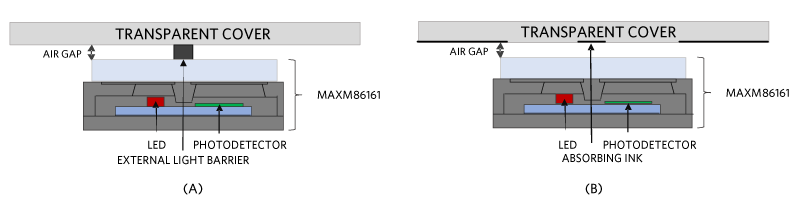
Figure 5. Light barriers (a) and inking (b).
Field of View
To maximize the incident light on the skin and the return signal on the photodetector, the emission area and field of view of the module should not be obstructed. For example, the elevator shaft type architecture shown in Figure 6 decreases the signal incident on the photodetector because the incident light on the skin is blocked or absorbed and not all of the signal is able to reach the photodetector.
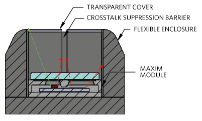
Figure 6. Field of view blockage. The red rays show light that could have contributed signal which instead is blocked by a large air gap and narrow opening.
Tissue Contact
Motion artifacts become dominant noise sources when the transparent cover is not properly coupled to the device and the tissue. Pliable materials can be used around the transparent cover to ensure the required skin contact for heart-rate detection.
Simulated Comparison of Critical Parameters
To evaluate the effects of the cover glass parameters, air gap, and crosstalk suppression features consider two key figures of merit for PPG measurements: perfusion index (PI) and crosstalk.
The PI is the AC/DC ratio of the detected PPG signal. The higher the PI, the better the performance. The optical signal incident on the photodetector consists of a large constant DC and a small variable AC component. The DC component contains no heart rate information, while the AC corresponds to the pulsing arterial blood[2] (Figure 7).
Crosstalk is signal that has not traversed through any skin and can be quantified by its crosstalk fraction, which is the ratio of signal that has not reached the skin to the total signal back on the photodetector. Higher crosstalk degrades the PPG signal and decreases the PI.
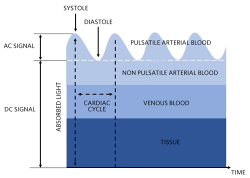
Figure 7. Light absorption of the skin and corresponding DC and AC levels.
A ray trace simulation demonstrated the effects of cover glass thickness, air gap, and barriers. The simulation used a Monte Carlo method to trace optical rays propagating in complex, inhomogenous, randomly scattering and absorbing media. The seven-layer model of the skin was used to simulate the optical properties of the ear.
First, the impact on crosstalk due to variations in air gap was simulated. Air gaps of 0.1mm to 1.5mm were evaluated for a Corning Gorilla Glass cover glass thickness of 0.4mm. As the air gap increased, the crosstalk naturally increased.
The effect of the increase in crosstalk on performance is evaluated by post-processing the simulation results to determine the PI change as a function of air gap. The results illustrate how damaging crosstalk is to PPG signal quality (Figure 8).
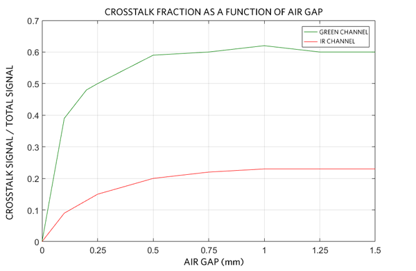
Figure 8. Crosstalk signal on the photodetector as a function of air gap.
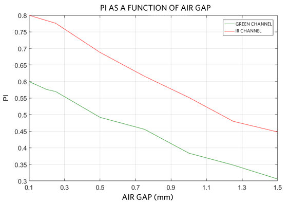
Figure 9. PI as a function of air gap.
Next, the impact on crosstalk due to variations in cover glass thickness was simulated. Simulations were conducted using Corning Gorilla Glass for thicknesses of 0.2mm to 1.0mm with a fixed air gap of 0.2mm. Results demonstrated that as the glass thickness increases, the crosstalk increases (Figure 10). This crosstalk is due to light being guided inside the glass from the LEDs to the photodetector. The effect on the PI due to the increase in crosstalk from increased cover glass thickness was determined by post-processing the simulation results (Figure 11).
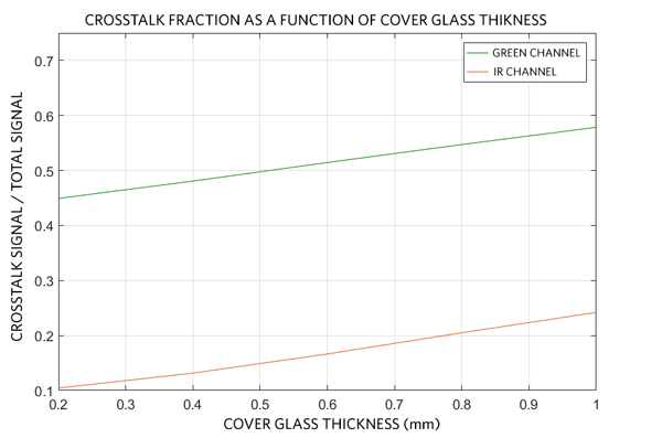
Figure 10. Crosstalk on the photodetector as a function of cover glass thickness.
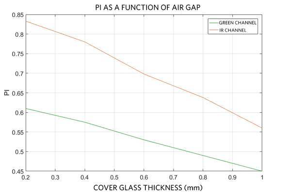
Figure 11. PI on the photodetector as a function of cover glass thickness.
As expected, the heart-rate monitor’s PPG signal is degraded when placed behind a cover glass due to the crosstalk introduced by the cover glass. This degradation becomes more severe as the thickness of the cover glass is increased. Additionally, the total signal back on the photodetector decreases as the thickness increases due to transmission loss through the cover glass. For these reasons, the thickness of the cover glass should be minimized. However, a cover glass that is too thin is too fragile and prone to chipping. Therefore, it is necessary to find a balance between performance and mechanical stability in the end customer’s industrial design.
Summary
The integration of LEDs, photodetector, IR sensor, and low-noise electronics into heart-rate measuring modules facilitates the ability to incorporate biosensing functionalities in consumer wearables such as earbuds. The performance of these modules depends greatly on their opto-mechanical integration into the end customer’s design. This application note outlines the key parameters to consider for successful integration of reflective heart-rate monitoring modules and discusses how each affects performance. To ensure the highest quality signal, use a high transmitting cover glass and minimize the air gap between the cover glass and the heart rate monitoring module. The cover glass thickness is a tradeoff between mechanical rigidity concerns and performance. External features such as barriers and absorptive inking can greatly reduce crosstalk between the LEDs and photodetector to enhance the PPG signal.
Related to this Article
Products
LAST TIME BUY
Integrated Heart-Rate Sensor for In-Ear Applications
PRODUCTION
Ultra-Low Power Biometric Sensor Hub
RECOMMENDED FOR NEW DESIGNS
Tiny, Ultra-Low-Power Arm Cortex-M4 Processor with FPU-Based Microcontroller (MCU) with 256KB Flash and 96KB S...
Product Categories
{{modalTitle}}
{{modalDescription}}
{{dropdownTitle}}
- {{defaultSelectedText}} {{#each projectNames}}
- {{name}} {{/each}} {{#if newProjectText}}
-
 {{newProjectText}}
{{/if}}
{{newProjectText}}
{{/if}}
{{newProjectTitle}}
{{projectNameErrorText}}
Latest Media 21


