FCC and ETSI Requirements for Short-Range UHF ASK-Modulated Transmitters
Abstract
There are governmental restrictions on intentional and unintentional radiated power from unlicensed transmitters used for remote keyless entry (RKE), home automation, home security, tire pressure monitoring systems (TPMS), and other applications requiring short-range devices (SRDs). These restrictions are established by regulatory agencies in each country or region. The two most influential agencies, based on the size of the markets that they impact, are the FCC in the United States and ETSI in Europe.
This application note describes the FCC and ETSI radiation limits that apply to amplitude-shift-keyed (ASK) transmitters in the ISM band that includes 315MHz, 433.92MHz, 868.35MHz, and 915MHz. The specific tests needed to demonstrate compliance with those limits, and the test parameters that can affect test results are all discussed. The calculated and measured spectrum of ASK modulation as well as spectrum-analyzer traces of transmissions from the MAX41462 ASK transmitter illustrate what is necessary to pass these tests.
Introduction
The Federal Communications Commission (FCC) in the US and the European Telecommunications Standards Institute (ETSI) in Europe both specify limits for radiated power levels of unlicensed transmitters used for remote keyless entry (RKE), home automation, home security, and other radio-controlled devices. The power limits apply both to the intended transmission and to the unintended, or spurious, transmission from these devices. Associated with these limits are test procedures for determining whether a device is radiating within the established guidelines. The relationship between the test instrumentation settings and the transmitter’s radiation characteristics is very important for the test outcome (i.e., a pass or fail).
This application note shows how the modulation spectrum of the amplitude-shift-keyed (ASK) signal, the transmitter’s phase noise, and the transient frequency pulling of the transmitter VCO all affect the qualification tests.
Note that this application note has been updated for the latest sub-1GHz regulatory ETSI requirements.
The ASK Modulation Spectrum
One way to understand the spectrum of ASK modulation is to start with a periodic square wave modulating an RF carrier and then “smear” the spectral lines to account for the random nature of a data stream.
To begin, think of the square wave of period 2T in Figure 1 as a 1010… non-return-to-zero (NRZ) data sequence with data rate 1/T. The power spectrum of this square wave is shown in Figure 2, where the zero frequency is taken to be the carrier frequency, f0. In this case, f0 consists of a line at the carrier, which we have normalized to unity, and lines at odd multiples of (1/2T). The ratio of the power in each line to the power in the carrier (zero frequency) line is defined as:
P(±n)/P(0) = (2/np)2, or in dB, -20log10(2/np)

Figure 1. Square wave of period 2T.

Figure 2. Power spectrum of a square wave of period 2T.
When the ASK modulation is true data, the randomness of the data leads to a power spectrum where each line is smeared into a half sine-wave cycle. The spectrum’s mathematical representation, normalized to the spectral density at the carrier frequency, is:
P(f)/P(0) = [sin(pfT)/pfT]2
The ratio of the spectral density’s peak at each sidelobe to the spectral density at the carrier frequency is still given by Equation 1.
Figure 3 shows the spectrum of the MAX41462 ASK transmitter. Notice that the sidelobe peaks are located at odd multiples of 5kHz, which is half the data rate.
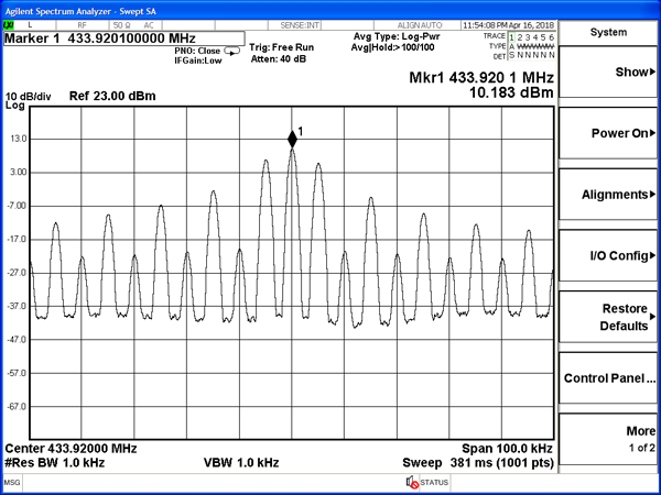
Figure 3. Spectrum of MAX41462 ASK transmitter with 10kHz modulation.
Note the relationship between the power in the carrier line (or lobe) of an ASK-modulated signal to the power of an unmodulated (CW) carrier. This is important because the FCC and ETSI regulations will sometimes apply to relative power and sometimes to absolute power. If a transmitter radiates a steady (unmodulated) carrier of P0 watts and is then modulated by a 50% duty-cycle ASK data stream, the total power radiated is cut in half, i.e., P0/2. Furthermore, because the modulation creates all those sidebands, only half of the power in the ASK-modulated signal is contained in the central (carrier) lobe of the spectrum. Consequently, when we talk about the power in a modulation sidelobe compared to the available CW power in a transmitter, the power ratio in Equation 1 can be reduced by another 6dB (the ratio of the CW power to the power in the carrier spectral lobe of an ASK modulated carrier).
As an example, a 315MHz transmitter that radiates 10mW of unmodulated carrier power radiates only 5mW of power when it is ASK modulated. Of the 5mW, 2.5mW is in the carrier lobe and the other 2.5mW is divided among the sidelobes. Therefore, for a data rate of 8kbps (see Equation 1), the power in the 101st sidelobe (404kHz from the carrier) is:
P(sidelobe) = +4dBm-20log10(2/101p) = +4dBm-44dB = -40dBm
Notice that the sidelobe power is not only 44dB below the power in the carrier lobe of the ASK modulated signal, but is also 50dB below the power in the unmodulated CW carrier.
FCC Requirements for ASK Transmitters
FCC Field Strength
For the ISM bands, the FCC Section 15.231 defines a maximum field strength based on a linear extrapolation from the defined band end points of 3.750mV/m at 260MHz to 12.5mV/m at 470MHz. To calculate this maximum value for frequencies between 260MHz and 470MHz, use the following equation:
E = 8.75/210×f–7.083
where E is the field strength in mV/m, and f is the frequency of operation in MHz. For any frequencies above 470MHz and under 900MHz, the FCC caps the field strength at 12.5mV/m. In the 902MHz to 928MHz band, the field strength limit is 500mV/m.
For unit translation of E(mV/m) to E(dBuV/m), use the following equation:
E = 20×log10(1000×E)
Emission Bandwidth
FCC Section 15.231(c)[1] states that the emission bandwidth (or occupied bandwidth (OBW)) of the intentional transmission shall be no wider than 0.25% of the center frequency, where the emission bandwidth is determined by the points in the radiated spectrum that are 20dB below the modulated carrier. For 315MHz and 433.92MHz, the two most-used frequencies in the 260MHz to 470MHz unlicensed band, the maximum allowable bandwidths are 787.5kHz (±394kHz) and 1.085MHz (±542kHz). For 915MHz, the maximum allowable bandwidth is 2.2875MHz.
From the formulas for the power in the ASK spectrum shown above, it is easy to predict the 20dB bandwidth of an ASK-modulated signal by determining the sidelobe whose power is at least 20dB less than from the power in the carrier frequency lobe. According to Equation 1, the 7th sidelobe power is 20.8dB less than the carrier frequency lobe power. Therefore, the 20dB bandwidth should be ±7 times half the data rate. For a 10kbps data rate, the 20dB emission bandwidth should be only 70kHz. At 500kHz from the carrier, which is approximately one side of the 0.25% bandwidth limit, the 10kbps spectrum should be 44dB less than the carrier frequency lobe.
In practice, the measured 20dB bandwidth is larger, and the spectral height 500kHz away is higher than these calculated values for three reasons:
- The FCC requires that the resolution bandwidth in the measurement equipment be wider than the modulation sidelobes;
- The phase noise from the synthesized oscillator adds power to the sidelobes;
- The ASK modulation pulls the VCO slightly, creating transient frequency components that show up in the measurements.
The FCC’s measurement bandwidth, which is the bandwidth setting on the measurement instrument, is not easy to determine and there are exceptions to it. FCC Section 15.231(b)(2)[1] refers to FCC Section 15.205, which refers to FCC Section 15.35, which, finally, refers to CISPR-16. CISPR-16 says that the measurement bandwidth for emissions below 1GHz is 120kHz if a quasi-peak detector is used, and 100kHz if a spectrum analyzer with a peak-detector function is used. For data rates that are a few kbps, this seems like a large measurement bandwidth to determine the emission bandwidth.
Fortunately, there is a narrower, more realistic, FCC measurement bandwidth specification. It does not appear in any documents, but is known by compliance testing companies and can be confirmed by inquiring on the FCC website under the Office of Engineering and Technology. This lesser-known specification says that the measurement bandwidth must be at least 1% of the allowable 20dB emission bandwidth. For 315MHz signals, therefore, 1% of the 787.5kHz bandwidth is roughly 8kHz, which can be satisfied by setting a spectrum-analyzer bandwidth to 10kHz. For 433.92MHz signals, 1% of the 1.085MHz bandwidth is slightly over 10kHz. This means that the spectrum analyzer bandwidth must be set to 30kHz, which is the next setting above 10kHz. For either signal (315MHz or 433.92MHz), the measurement bandwidth is lower than 100kHz.
The phase-noise spectral density in a PLL transmitter can vary widely from one manufacturer to another. The Maxim series RF CMOS transmitters have phase-noise densities between -85dBc/Hz and -90dBc/Hz when measured 500kHz from the carrier. This means that the phase noise measured in the maximum FCC bandwidth of 100kHz will be at least 35dB less than the carrier power 500kHz from the carrier. The presence of phase noise will raise the measured modulated spectrum for low data rates whose theoretical sidelobe power levels are more than 35dB below the carrier-lobe power when measured 500kHz from the carrier.
The transient pulling of the VCO from ASK modulation can add 5dB to the measured spectral height if wide measurement bandwidths (e.g., 100kHz) are used. While these transients exist for only a few microseconds, they can be detected by a wide-resolution filter with a “Max Hold” feature. Reducing the filter resolution bandwidth to 30kHz or lower dramatically eliminates any effect on the measured spectrum from this phenomenon.
The peak detector, or “Max Hold” setting, required by the FCC can raise the measured power of these three contributions by as much as 10dB. Consequently, an emission bandwidth measurement may show a spectrum that is only 20dB to 25dB lower than the carrier power 500kHz from the carrier, even though the theoretical modulation spectrum is really 35dB to 55dB lower. This large difference between the theoretical and measured spectra can create a problem in passing the FCC tests at high data rates because the FCC requires the spectrum from all contributions to be only 20dB below the carrier-lobe power at roughly 500kHz from the carrier. Table 1 shows the theoretical spectral height of the ASK modulation sideband 500kHz from the carrier for different data rates. It also shows the power that would be measured in 100kHz, 30kHz, and 10kHz bandwidths.
| Data Rate (kbps) | Sideband Number at 500kHz | Sideband (dBc) | dBc in 100kHz BW | dBc in 30kHz BW | dBc in 10kHz BW |
| 2 | 501 | -58 | -41 | -46 | -51 |
| 4 | 251 | -52 | -38 | -43 | -48 |
| 8 | 126 | -46 | -35 | -40 | -45 |
| 10 | 101 | -44 | -34 | -39 | -44 |
| 20 | 51 | -38 | -31 | -36 | -41 |
| 100 | 11 | -25 | -25 | -28 | -32 |
Figure 4 and Figure 5 show the measured spectrum for the MAX41462 ASK transmitter IC, modulated at a 10kbps data rate, using 100kHz and 30kHz bandwidths. The difference between these calculated levels and the measured levels comes from the phase-noise contribution, the transient pulling on the VCO, and the “Peak Hold” measurement technique. Notice that using the 30kHz resolution bandwidth increases the margin for meeting the emission bandwidth requirement. In Figure 4, the point in the radiated spectrum that is 20dB below the modulated carrier is located at 365kHz away from the center frequency. However, in Figure 5 with the 30kHz resolution bandwidth, that number reduces to 230kHz.

Figure 4. MAX41462 spectrum modulated by 5kHz square wave measured for FCC emission bandwidth with 100kHz resolution bandwidth.

Figure 5. MAX41462 spectrum modulated by 5kHz square wave measured for FCC emission bandwidth with 30kHz resolution bandwidth.
Spurious Emissions
FCC Section 15.231(b)(3)[1] states that the field strength of spurious emissions must be held to defined levels shown in a table in that section. This table sets limits on the intentional transmission at the carrier frequency and the spurious transmissions outside the emission bandwidth. These spurious field-strength levels are 20dB below the maximum allowable intentional transmission levels. This means that if the transmitter is radiating the maximum allowable level, then anything radiated outside the emission bandwidth has to be more than 20dB below the carrier power level. This conveniently coincides with the 20dB emission bandwidth requirement when the maximum power is radiated. The spurious radiation is measured with a quasi-peak detector per CISPR-16 or with a spectrum analyzer using a peak detector. This process is very much like the measurement for emission bandwidth, except that the spectrum-analyzer bandwidth is 100kHz.
One should note that, if the transmitter is not radiating at the maximum allowable power, the maximum spurious emission level remains at the absolute field-strength values defined in the table. In this case, the spurious radiation may not need to be as much as 20dB below the intentional radiated power outside the emission bandwidth.
ETSI Requirements for ASK Transmitters
In Europe, transmitted signals as high as 10mW (+10dBm) are allowed in the 433.05MHz to 434.79MHz band, and normally 25mW (+14dBm) are allowed in the 863MHz to 870MHz band.
Out-of-band Emissions
Two out-of-band (OOB) domains are defined: one for the operating channel (see Figure 6) and one for the operational frequency band (see Figure 7). The spectrum masks for these two OOB domains might overlap.
The ETSI defines out-of-band emissions as follows:
“Unwanted emissions in the out-of-band domain are those falling in the frequency range immediately below the lower, and above the upper, frequency of the Operating Channel. The OOB domain includes both frequencies outside the Operating Channel within the Operational Frequency Band and frequencies outside the Operational Frequency Band.”
Figure 6 shows the out-of-band domain for the operating channel.

Figure 6. Out-of-band domain for operating channel with reference BW.
The relevant out-of-band domain is shown in Figure 6 and applies within the operational frequency band. Specific limits apply at frequencies immediately above and below the operational frequency band, as shown in Figure 7.

Figure 7. Out-of-band domain for operational frequency band with reference BW.
Section 3.1 in the ETSI EN 300 220-1 V3.1.1 defines the operating channel (OC) and operating channel width (OCW) as follows:
- Operating Channel (OC): The frequency range in which the transmission from the equipment occurs defined by two frequency edge values (FLOW and FHIGH) declared by the manufacturer.
- Operating Channel Width (OCW): The bandwidth between the two frequencies (FLOW and FHIGH) declared as the operating channel.
We used the typical values of OCW = 200kHz and 300kHz as examples in this application. Equation 1 through Equation 3 can be used to form Table 2, which is similar to Table 1 except that the distance from the carrier is 500kHz (OCW = 200kHz) and 750kHz (OCW = 300kHz).
| Data Rate (kbps) | Sideband Number at 500kHz | Sideband (dBc) | Sideband Number at 750kHz | Sideband Number at 750kHz (dBc) |
| 2 | 501 | -58 | 751 | -62 |
| 4 | 251 | -52 | 376 | -56 |
| 8 | 126 | -46 | 189 | -50 |
| 10 | 101 | -44 | 151 | -48 |
| 20 | 51 | -38 | 76 | -42 |
| 100 | 11 | -25 | 16 | -28 |
The emissions level in out-of-band domains for the operating channel must be less or equal to the spectrum mask as shown in Table 3.
| Domain | Frequency Range | RBWREF | Max power limit |
| OOB limits applicable to Operational Frequency Band (See Figure 6) | f = flow_OFB-400kHz | 10kHz | -36dBm |
| flow_OFB - 400kHz = f = flow_OFB - 200kHz | 1kHz | -36dBm | |
| flow - 200kHz = f < flow_OFB | 1kHz | See Figure 6 | |
| f = flow_OFB | 1kHz | 0dBm | |
| f = fhigh_OFB | 1kHz | 0dBm | |
| fhigh_OFB < f = fhigh_OFB + 200kHz | 1kHz | See Figure 6 | |
| fhigh_OFB + 200kHz = f = fhigh_OFB + 400kHz | 1kHz | -36dBm | |
| fhigh_OFB + 400kHz = f | 10kHz | -36dBm | |
| OOB limits applicable to Operating Channel (See Figure 5) | f = fc- 2.5 x OCW | 1kHz | -36dBm |
| fc - 2,5 x OCW = f = fc - 0,5 x OCW | 1kHz | See Figure 5 | |
| f = fc - 0,5 x OCW | 1kHz | 0dBm | |
| f = fc + 0,5 x OCW | 1kHz | 0dBm | |
| fc + 0,5 x OCW = f = fc + 2,5 x OCW | 1kHz | See Figure 5 | |
| f = fc + 2,5 x OCW | 1kHz | -36dBm | |
| NOTE: f is tde measurement frequency. fc is tde Operating Frequency. Flow_OFB is tde lower edge of tde Operational Frequency Band. Fhigh_OFB is tde upper edge of tde Operational Frequency Band. OCW is tde operating channel bandwidtd. |
|||
The spectrum analyzer must be configured as appropriate for the parameters shown in Table 4.
| Spectrum Analyser Setting | Value | Notes |
| Centre frequency | Operating Frequency | |
| Span | 6 x Operating Channel width | |
| RBW | 1kHz (see note) | Resolution bandwidth for Out Of Band domain measurements |
| Detector Function | RMS | |
| Trace Mode | Linear AVG | Applies only for EUT generating D-M2 test signal. An appropriate number of samples should be averaged to give a stable reading |
| Max Hold | Applies only for EUT generating D-M2a or D-M3 test signal. | |
| NOTE: If the value of RBW used is different from RBWREF in clause 5.8.2, use the bandwidth correction in clause 4.3.10.1. |
||
For example, a 433.92MHz transmitter modulates at a 10kbps data rate. Each sideband is centered at an odd multiple of 5kHz. We used 200kHz as the operating channel width. This means that the 101st harmonic sideband of 5kHz is the first complete sideband to be more than 500kHz (2.5×OCW) from the carrier, and that the total power in this sideband must be below -36dBm (ETSI limit).
According to Table 2, the power in the 101st sideband is -44dBc compared to the carrier-lobe power. Assume the transmitter radiates full +10dBm of the unmodulated carrier, the 50% duty-cycle ASK data stream modulated carrier-lobe power is 6dB down, which gives the carrier-lobe power as +4dBm. That means the 101st sideband power is -40dBm (sideband is -44dBc), which is well below the -36dBm limit. Nonetheless, in practice the measured sidelobe power at 500kHz away from carrier-lobe is always higher than the calculated value. As with the FCC regulations, the level of transmitter phase noise and the transient pulling on VCO combine to raise the measured power level higher than the theoretical value.
Figure 8 shows the spectrum of the MAX41462 ASK transmitter with a 433.92MHz carrier, modulated at a 10kbps data rate. The maximum unmodulated carrier power is +10dBm (OCW = 200kHz).

Figure 8. The MAX41462 spectrum modulated by 5kHz square wave measured for ETSI out-of-band emissions for operating channel.
The spectrum analyzer settings used for the measurement of Figure 8 are as follows:
- Center frequency: 433.92MHz
- Span: 1.2MHz
- RBW: 1kHz
- Trace mode: Average
- Spectrum analyzer model: Agilent® EXA N9010A
Figure 9 shows the operational frequency band measurements according to the requirements shown in Figure 7 (OFB = 400kHz).

Figure 9. The MAX41462 spectrum modulated by 5kHz square wave measured for ETSI out-of-band emissions for operational frequency band.
Spurious Emissions
Section 5.9.1 in the ETSI EN 300 220-1 V3.1.1 defines spurious emissions as unwanted emissions in the spurious domain at frequencies other than those of the operating channel and its out-of-band domain. The relevant spurious domain is shown in Figure 10.

Figure 10. Spectrum mask for unwanted emissions in the spurious domain with reference BW.
This measurement is intended to look for unintentional mixer products or clock harmonics, not for the spectral power that result from modulating the carrier. This measurement is made with an unmodulated carrier where possible, so the modulation sidebands are not an issue. The power level of the transmitter phase noise in the measurement bandwidth needs to be considered for this measurement.
In the spurious domain, the transmitted power of unwanted emissions must not exceed –54dBm for the frequency ranges of 47MHz to 74MHz, 87MHz to 118MHz, 174MHz to 230MHz, and 470MHz to 790MHz. For other frequencies below 1GHz, the transmitted power must not exceed –36dBm. For frequencies above 1GHz, the transmitted power must be less than –30dBm.
The power is measured differently than for the modulation sidebands in section 5.8 in the ETSI EN 300 220-1 V3.1.1. For a different frequency range, a different resolution bandwidth is performed, as shown in Table 5.
| Operating Mode | Frequency Range | RBWREF (see note 2) |
| Transmit mode | 9kHz = f < 150kHz | 1kHz |
| 150kHz = f < 30MHz | 10kHz | |
| 30MHz = f < fc - m | 100kHz | |
| fc - m = f < fc - n | 10kHz | |
| fc - n = f < fc - p | 1kHz | |
| fc + p < f = fc + n | 1kHz | |
| fc + n < f = fc + m | 10kHz | |
| fc + m < f = 1 GHz | 100kHz | |
| 1 GHz < f = 6 GHz | 1MHz | |
| NOTE 1: f is the measurement frequency. fc is the Operating Frequency. m is 10 x OCW or 500kHz, whichever is the greater. n is 4 x OCW or 100kHz, whichever is the greater. p is 2,5 x OCW. NOTE 2: If the value of RBW used for measurement is different from RBWREF, use bandwidth correction from clause 4.3.10.1. |
||
For conducted measurement, the MAX41462 is connected to the spectrum analyzer which is used as an external receiver. For example, if 433.92MHz is applied as the transmitting carrier frequency and 200KHz is applied as the operating channel width, the spectrum analyzer frequency and RBW settings to measure spurious emissions are shown in Table 6.
| Frequency Range 10MHz to 433.92MHz-2.5*OCW (OCW=200kHz) | RBW/kHz | ETSI Limit/dBm | Frequency Range 433.92MHz+2.5*OCW to 6GHz (OCW=200kHz) | RBW/kHz | ETSI Limit/dBm |
| 10MHz-30MHz | 10 | -36 | 434.42MHz-434.72MHz | 1 | -36 |
| 30MHz-47MHz | 100 | -36 | 434.72MHz-435.92MHz | 10 | -36 |
| 47MHz-74MHz | 100 | -54 | 435.92MHz-470MHz | 100 | -36 |
| 74MHz-87.5MHz | 100 | -36 | 470MHz-790MHz | 100 | -54 |
| 87.5Mhz-118MHz | 100 | -54 | 790MHz-1GHz | 100 | -36 |
| 118MHz-174MHz | 100 | -36 | 1GHz-6GHz | 1000 | -30 |
| 174MHz-230MHz | 100 | -54 | |||
| 230MHz-431.92MHz | 100 | -36 | |||
| 431.92Mhz-433.12MHz | 10 | -36 | |||
| 433.12Mhz-433.42Mhz | 1 | -36 |
Figure 11, Figure 12, and Figure 13 show the measurements for the MAX41462 with +10dBm unmodulated power.

Figure 11. Unwanted spurious emissions 10MHz to 433.92MHz – 2.5×OCW (OCW = 200kHz).

Figure 12. Unwanted spurious emissions 433.92MHz + 2.5 × OCW to 1GHz (OCW = 200kHz).

Figure 13. Unwanted spurious emissions 1GHz to 6GHz.
In the range of 431.92MHz to 433.12MHz as shown in Figure 11, the measured power means the average power in a 10kHz bandwidth. This means that the radiated power density of a noise-like signal (e.g., phase noise) can be no higher than -76dBm/Hz (-36dBm divided by noise in the 10kHz bandwidth) more than 800kHz (4 × OCW) from the carrier. If the transmitter CW power is +10dBm, then the transmitter's phase-noise density must be lower than -86dBc/Hz (-76dBm/Hz divided by the +10dBm of the unmodulated carrier). Similarly, in the range of 30MHz to 431.92MHz, a 100KHz bandwidth is applied. That means the transmitter’s phase-noise density at 2MHz (10 × OCW) away from the carrier needs to be lower than -96dBc/Hz. By practical measurement, we obtained that the MAX41462 phase noise at 2MHz is about -96.5dBc/Hz.
For other Maxim transmitters such as the MAX1472 and MAX7044, the phase-noise spectral density is about -91dBc/Hz at 2MHz (10 × OCW) away from the carrier so that these devices exceed the ETSI requirement by 5dB if they radiate the full +10dBm CW power. These devices can be operated at reduced power (+5dBm) without violating the ETSI requirements.
Users should be aware that the above data is measured with lab-use equipment (i.e., Keysight® power meter, spectrum analyzer, signal source analyzer). However, in a practical application, the radiated signal is reduced significantly when the transmitting output connects to a low profile or PCB antenna. Low profile and PCB antenna usually have more loss and, as a consequence, the radiated signal meets the 36dBm power requirement.
The phase-noise spectral density of the MAX1479 is around -98dBc/Hz at 800kHz from the carrier, so it can be operated at the full +10dBm power level permitted by ETSI. The -54dBm requirement in the 470MHz to 862MHz range converts to a phase noise density of -114dBc/Hz. All Maxim transmitters meet this power level because the lower frequency edge of the region where this is required (470MHz) is so far removed in frequency from the carrier that the only noise radiated comes from the transmitter's thermal noise floor.
The content used in Figure 6, Figure 7, Figure 10, Table 3, Table 4, and Table 5 are from the ETSI EN 300 220-1 V3.1.1 standard and used with permission from the European Telecommunications Standards Institute.
© European Telecommunications Standards Institute 2017. Further use, modification, copy and/or distribution are strictly prohibited.
{{modalTitle}}
{{modalDescription}}
{{dropdownTitle}}
- {{defaultSelectedText}} {{#each projectNames}}
- {{name}} {{/each}} {{#if newProjectText}}
-
 {{newProjectText}}
{{/if}}
{{newProjectText}}
{{/if}}
{{newProjectTitle}}
{{projectNameErrorText}}
Latest Media 21


