Considerations for Fuel Gauging Lithium-Iron-Phosphate Batteries
Abstract
Certain high C-rate applications are powered by lithium iron phosphate (LiFeP04 or LFP) batteries. These battery types require special care when it comes to fuel gauging. This application note covers the unique features of these battery types and shares test results using a fuel-gauging algorithm configured for LFP batteries.
Introduction
The volume of lithium-ion (Li+) batteries used worldwide continues to grow every year. These batteries boast high energy densities, low rates of self-discharge, and negligible memory effects. There are numerous variations of Li+ batteries on the market, each with their own unique characteristics. These batteries can be combined into types based on their chemistries. Each chemistry type has its own advantages and drawbacks for delivering power to specific applications. Table 1 shows the main types of Li+ batteries. This application note focuses on lithium iron phosphate (LFP) batteries as a use case highlighting fuel-gauging considerations to drive greater accuracy.
| Battery Chemistry | Description |
| Lithium Cobalt Oxide (LCO) | LCO is one of the most common types of Li+ batteries used today. Because of its very high energy density, it is used as an energy cell. Its power density is limited, and the materials used in production are relatively expensive, especially cobalt. |
| Lithium Manganese Oxide (LMO) | LMO is more stable than LCO. It is used in high-power cells, but has lower energy density. To enhance performance, LMO may be combined with NMC chemistry. |
| Lithium Nickel Manganese Cobalt Oxide (NMC) | NMC provides high capacity and power and may be combined with LMO batteries for better stability. |
| Lithium Nickel Cobalt Aluminum Oxide (NCA) | Similar to batteries with LCO chemistry, NCA is primarily used in applications requiring high energy density. |
| Lithium Titanate (LTO) | LTO is one of the safest Li+ chemistries. These batteries can be charged quickly, have long lives, and can operate over wide temperature ranges. These batteries are relatively expensive and have low specific energy. |
| Lithium Iron Phosphate (LiFePO4 or LFP) | LFP is one of the safest Li+ chemistries and is known for having a very flat voltage discharge curve. Lithium iron phosphate is used in the cathode of these batteries, while carbon is used in the anode. Compared to other chemistries, these batteries typically have low capacity and higher self-discharge. They can be used over a wider range of temperatures than most Li+ batteries. |
LFP Batteries—A Primer
Advantages
Compared to lead-acid and other types of lithium batteries, LFP batteries are thermally and chemically more stable. They do not combust, even during fault conditions such as overcharge or short circuit, and are not prone to thermal runaway. The batteries may also be used over a wider range of temperatures than other Li+ batteries: -40°C to +70°C. LFP batteries also offer longer cycle life, from 1000 to 2000 cycles, compared to the sub-1000 cycles typical of LCO, LMO, NMC, and NCA cells. LFP cells may be exposed to high voltages for a prolonged time with much lower stress than other chemistries. They may be discharged up to a very high 25C rate. By comparison, other Li+ batteries typically discharge at under 1C, though in some extreme cases they may discharge at up to 10C.
Drawbacks
LFP batteries have lower nominal voltage of 3.2V, which means that the specific energy is lower than the 3.6V to 3.8V nominal range of LCO, LMO, NMC, and NCA cells. The cells are also sensitive to moisture and water. When these batteries come in direct contact with water, it causes a loss of active material in the cathode, which reduces the material's energy density. Therefore, only high-quality cells, manufactured under strict quality control, can tolerate moderate external moisture conditions. Just like batteries with other chemistries, LFP batteries tend to perform worse at colder temperatures.
Typical Applications
LFP batteries are used in a wide variety of high C-rate applications. Some examples include small electric vehicles, electric green mowers, scissor lifts, garbage trucks, robotics, home energy storage, hybrid generators, and truck APU systems. Other applications for this battery type are weather monitoring devices, ocean buoys, oil and gas pipeline equipment, license plate monitoring devices, depth finders, paddle boards, and playground equipment.
Challenges of Monitoring LFP Batteries
LFP batteries have very flat discharge curves and hysteresis, which makes it very difficult to monitor these cells. Figure 1 shows a typical discharge curve of an LFP battery. In some regions, voltage barely drops as the battery gets discharged for an extensive amount of time. Figure 2 shows the hysteresis of LFP cells and the associated state-of-charge (SOC) error. In contrast, Figure 3 shows a typical discharge curve of an NCA battery, where voltage drops significantly during discharge.
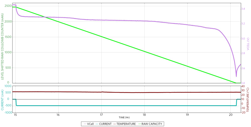
Figure 1. A typical discharge curve of an LFP battery.
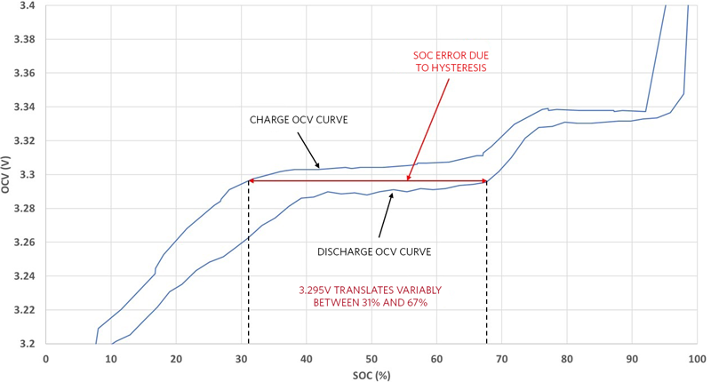
Figure 2. Hysteresis in LFP cells and an associated SOC error of 35%.

Figure 3. A typical discharge curve of an NCA battery.
Other battery chemistries with behavior similar to that of LFP cells include lithium cobalt phosphate (LiCoPO4), lithium iron sulphate fluoride (LiFeSO4F), and lithium manganese phosphate (LiMnPO4).
Accurate LFP Battery Fuel Gauging
LFP cells have extremely flat voltage profiles, where just 1% of the SOC change corresponds to only a few millivolts of change on the open-circuit voltage (OCV) curve. Furthermore, LFP cells are known for their hysteresis in the OCV curve. Fortunately, techniques are available to derive higher accuracy when monitoring LFP cells. For example, a continual OCV prediction algorithm (without requiring relaxed, full, or empty conditions) combined with a coulomb counter has demonstrated greatly diminished voltage sensitivities vs. other coulomb-counting methods. Most alternative methods require observing the battery in a relaxed state and performing corrections based on the measured voltage. In such methods, the corrections are infrequent (a few times per day instead of many small corrections per minute), and the impact of any error during the correction is significant. Any error during the correction is normally frozen in and, therefore, persists until the next correction. Because of this, the choice of algorithm and its use of voltage are especially critical with LFP batteries. An optimal algorithm minimizes these errors by always giving small weight to the voltage corrections. Therefore, it is much more resilient to voltage measurement error.
Cell Under Test
Using the OCV algorithm with coulomb counting, a test was performed on the ANR26650M1-B LFP cell, which has a nominal capacity of 2500mAh.
Well-tuned fuel gauges have demonstrated the ability to provide excellent fuel-gauging accuracy. We chose a test pattern that pushes the fuel gauge to extremes, where the battery is continually used without reaching full or empty for more than a week. Monitoring such a pattern is very challenging, even in the case of non-LFP cells. The curve in Figure 4 shows better than a 2% SOC error during the test pattern.

Figure 4. Test pattern showing battery voltage, current, temperature, and SOC error. Except for the first cycle, the SOC error remained under 2%.
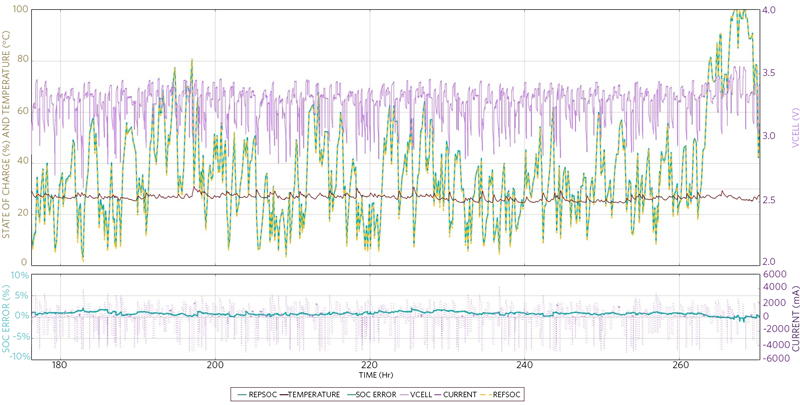
Figure 5. Accurate fuel gauging was achieved during the complex case of continuous use without reaching full or empty for more than a week. The error remained under 2%.

Figure 6. The SOC error remained under 2%, even at -5°C.
Example Fuel-Gauge IC for LFP Batteries
This test case used the MAX17201 fuel-gauge to monitor an LFP battery; any other IC in the MAX17201/MAX17211/MAX17205/MAX17215 family would yield similar results. The OCV-SOC curve of an LFP battery is much flatter than conventional lithium-cobalt chemistries, thus producing a greater sensitivity to the algorithm's interpretation of cell voltage and OCV. In order for the fuel-gauge algorithm to achieve an accurate, full-capacity measurement over time, the battery's full capacity needs to be calculated outside the keep-out window, which has the flattest region and most hysteresis in the OCV-SOC curve. To calculate this with the MAX17201, full-capacity learning uses charge sessions and discharge sessions accumulated only when relaxation occurs outside the keep-out window (e.g., 20% to 72%), when enabled. There also must be an SOC change of more than 2% for the learning to take place.
Figure 7 shows an OCV-SOC curve of an LFP cell, as well as an OCV keep-out region.

Figure 7. The OCV-SOC curve for an LFP cell with the OCV keep-out region. To prevent incorrect learning, this region is not used to calculate full capacity.
Perform these steps to configure the MAX17201 ModelGauge™ m5 family for LFP support:
- Send the battery or battery data to Maxim (through your field application engineer) for characterization. The characterization data should be translated by Maxim into a battery model.
- Set enSC to 1 in the nNVCfg1 (1B9h) register to enable LFP mode and window blocking.
- Load the rest of the battery model. For more details, see the MAX1720x/MAX1721x Software Implementation Guide.
The MAX17055 and MAX17260/MAX17261/MAX17263 support LFP batteries with a special model configuration. For good SOC accuracy, it is necessary to characterize and model the specific LFP cells being used. These ICs provide additional algorithm support specifically for the challenges associated with LFP and other "flat" OCV chemistries.
Follow this process to configure the MAX17260/MAX17261/MAX17263 and MAX17055 for LFP support:
- Send the battery or battery data to Maxim (through your field application engineer) for characterization. The characterization data should be translated by Maxim into a battery model.
- Write 0x0060 to the ModelCFG (DBh) register to enable LFP mode and window blocking.
- Load the rest of the battery model. For more details, see the MAX17055 Software Implementation Guide and the MAX1726x Software Implementation Guide.
Summary
LFP batteries are ideal for certain high C-rate applications; however, accurate fuel-gauging of these battery types requires special care. This application note discussed a test case using an OCV fuel-gauging algorithm with coulomb counting. This type of algorithm overcomes some of the accuracy challenges that other fuel-gauging methods encounter with LFP batteries.
Related to this Article
Products
PRODUCTION
Stand-Alone ModelGauge m5 Fuel Gauge with SHA-256 Authentication
RECOMMENDED FOR NEW DESIGNS
Stand-Alone ModelGauge m5 Fuel Gauge with SHA-256 Authentication
PRODUCTION
Single/Multi-Cell Fuel Gauge with ModelGauge m5 EZ and Integrated LED Control
Stand-Alone ModelGauge m5 Fuel Gauge with SHA-256 Authentication
5.1µA Multi-Cell Fuel Gauge with ModelGauge m5 EZ
5.1µA 1-Cell Fuel Gauge with ModelGauge m5 EZ and Optional High-Side Current Sensing
7µA 1-Cell Fuel Gauge with ModelGauge m5 EZ
Product Categories
{{modalTitle}}
{{modalDescription}}
{{dropdownTitle}}
- {{defaultSelectedText}} {{#each projectNames}}
- {{name}} {{/each}} {{#if newProjectText}}
-
 {{newProjectText}}
{{/if}}
{{newProjectText}}
{{/if}}
{{newProjectTitle}}
{{projectNameErrorText}}
Latest Media 21


