Consider Overall Cascaded Performance When Comparing Integrated RF Frequency\r\nMixers to Passive Mixer Solutions
Abstract
The following application note compares the features of an integrated RF and passive mixer solution. It discusses the main features of both solutions and shows the main advantages of an integrated over a passive solution.
In the past, RF designers have used passive down-conversion mixers to obtain the best overall linearity and spurious performance for their high performance receiver designs. There are several disadvantages when using discrete passive mixers in these designs.
Passive mixers have insertion loss that requires compensation in either the RF or IF gain stages to establish the overall desired receiver noise figure performance. For these passive mixers, the user must not only consider the third-order input intercept points (IIP3), but should also consider the output third-order intercept point (OIP3) when comparing the performance to integrated mixers. Passive mixers seldom have second order linearity performance as good as an integrated balanced mixer design, which is important for receiver half-IF spurious considerations. Because a mixer's linearity performance is directly related to the LO drive level, rather large LO injection signals must be generated and then routed on the PC board to the passive mixer's LO port. External RF stages are needed to amplify these signals making the whole design susceptible to both LO radiation and pick-up. Finally, passive mixers typically lead to an all-discrete design resulting in higher cost, larger PC board space, and larger performance variation due to discrete part-to-part tolerance.
Integrated (or active) mixer designs are becoming more popular as their performance rivals that of passive mixer solutions. An integrated mixer might consist of a true balanced (Gilbert Cell) design or passive mixer with an IF amplifier stage resulting in gain instead of loss. Because the integrated mixer has gain, an external IF amplifier stage is not needed to make up for the loss that's required when using a passive mixer. For integrated mixers with superb noise figure performance such as Maxim's MAX9993, MAX9981, and MAX9982, less RF gain is needed ahead of the mixer stage, which translates to better overall receiver linearity performance. Restated, as more gain is added in front of the mixer to minimize the cascaded noise figure, the mixer's linearity performance must be increased to maintain overall receiver linearity. LO drive circuits are included in Maxim's MAX9993, MAX9981, and MAX9982 mixers as an added benefit.
Consider Maxim's MAX9993 High-Linearity down-conversion mixer having the following functionality as shown in Figure 1:

Figure 1. MAX9993 equivalent circuit.
The nominal specifications for the MAX9993 in the PCS & UMTS frequency bands are:
- Conversion Gain = 8.5dB
- Noise Figure = 9.5dB
- IIP3 = +23.5dBm
- OIP3 = +32dBm
- IIP2 = +60dBm
- OIP2 = +68.5dBm
- Low LO drive level: 0 to +6dBm
- Two switch-selectable (SPDT) LO inputs for GSM application (the LO switch can be static for non-switching applications such as cdma2000®)
Figure 2 illustrates a discrete solution using a passive mixer, IF amplifier, and LO amplifier. This figure assumes single-ended components are used, which results in inferior 2nd order linearity performance compared to Maxim's integrated mixer family. When reviewing an integrated RF frequency mixer data sheet, the RF circuit designer must consider the equivalent cascaded response of the individual discrete stages in a passive design in order to make a fair comparison to Maxim's integrated mixers. For example, a designer cannot only look at the passive mixer's 3rd order input intercept point, but must also consider its 3rd order output intercept performance and the overall cascaded response including the IF amplifier stage(s) which follows. In addition, the designer must calculate the equivalent gain and noise figure of the passive mixer solution and compare the results to the integrated mixer specifications.
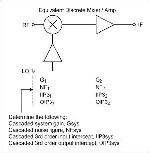
Figure 2. Discrete mixer / IF amp.
For each of the stages, the following notation is used:
G = conversion power gain
NF = noise figure
IIP3 = input 3rd order intercept point
OIP3 = output 3rd order intercept point
Example:
Refer to Figure 2. Calculate the IF amplifier specifications that are needed to obtain an overall cascaded response equal to the MAX9993 performance for gain, noise figure, and 3rd order intercept point. Assume the Mini-Circuits® HJK-19MH passive mixer is used with the nominal specifications in the PCS & UMTS frequency bands given as:
G1 = -7.5dB
NF1 = 7.5dB (assumed)
IIP31 = +29dBm
OIP31 = IIP31 + G1 = +21.5dBm
Use the MAX9993 typical specifications as the typical system parameters in the PCS & UMTS frequency bands:
Gsys = overall system gain = +8.5dB
NFsys = overall system noise figure = 9.5dB
IIP3sys = overall system input 3rd order intercept point = +23.5dBm
OIP3sys = overall system output 3rd order intercept point = +32dBm
Required IF amplifier gain:
Determine the required IF amplifier gain from the following:
Gsys = 8.5dB
= G1 + G2 so solving for G2,
G2 = Gsys - G1 = 8.5dB - (-7.5dB)
= 16dB
Required IF amplifier noise figure:
In order to obtain a cascaded noise figure performance of 9.5dB and assuming the passive mixer noise figure equals 7.5dB, determine the required IF amplifier noise figure using the well known cascaded noise factor equation where noise figure (in dB) equals 10 * log (Noise Factor) where Noise Factor is numeric.
NFsys = 9.5dB
= 10 * log (System Noise Factor)
= 10 * log (Fsys)
= 10 * log (F1 + (F2 - 1) / G1)
Solve for NF2 using:
NF2 = 10 * log ((Fsys - F1) * G1 + 1)
= 10 * log ((10^(9.5 / 10) - 10^(7.5 / 10)) * (10^(-7.5 / 10)) + 1)
= 10 * log ((8.91 - 5.62) * 0.18 + 1)
= 10 * log (1.59)
= 2dB
Required IF amplifier 3rd order intercept performance:
Determine the IF amplifier IIP3 requirement using the cascaded input intercept equation:
IIP3sys (dBm) = +23.5dBm
= 10 * log (IIP3numeric)
= 10 * log (1 / (1/10^(IIP31 / 10) + 10^(G1 / 10) / 10^(IIP32 / 10)))
Solve for IIP32 in order to determine the required 3rd order intercept point of the IF amplifier stage:
IIP32 (dBm) = 10 * log (10^(G1 / 10) * (1 / (1 / 10^(IIP3sys / 10) - 1 / 10^(IIP31 / 10))))
= 10 * log (10^(-7.5/10) * (1 / (1 / 10^(23.5 / 10) - 1 / 10^(29 / 10))))
= 17.5dBm
This IIP32 value results in the following 3rd order output intercept point for the amplifier:
OIP32 (dBm) = OIP32 + G2
= +17.5dBm + 16dB
= +33.5dBm
Cascaded Results:
The equivalent cascaded parameters are summarized in Figure 3 below:

Figure 3. Passive mixer & IF amplifier values for desired cascaded response.
From the calculated IF amplifier specifications, not only would it be difficult to find an IF amplifier with gain of 16dB combined with a noise figure of 2dB, but the superb 2nd order linearity performance of the MAX9993 could not be realized using this discrete solution. In addition, at least one and possibly two external LO amplifiers would be required to generate the +13dBm LO drive level needed to drive the Mini-Circuits HJK-19MH mixer.
Conclusion
A prudent receiver circuit designer should not dismiss the idea of using an integrated mixer solution without first calculating the equivalent cascaded performance of the discrete solution and comparing it to Maxim's integrated mixers. The advantages of using an integrated mixer solution over a discrete mixer solution discussed above are clear. The most important parameters that must be taken into consideration when comparing these two solutions include conversion gain, noise figure, and linearity (mainly 2nd and 3rd order). The proper way to calculate these cascaded parameters has been shown in this application note.
Related to this Article
Products
825MHz to 915MHz, SiGe High-Linearity Active Mixer
LAST TIME BUY
High-Linearity 1700MHz to 2200MHz Down-Conversion Mixer with LO Buffer...
825MHz to 915MHz, Dual SiGe High-Linearity Active Mixer
Product Categories
{{modalTitle}}
{{modalDescription}}
{{dropdownTitle}}
- {{defaultSelectedText}} {{#each projectNames}}
- {{name}} {{/each}} {{#if newProjectText}}
-
 {{newProjectText}}
{{/if}}
{{newProjectText}}
{{/if}}
{{newProjectTitle}}
{{projectNameErrorText}}
Latest Media 21


