Abstract
This note is a checklist of details that need to be done correctly for the MAX3420E to operate properly. A methodical verification process and debug hints are included.
Introduction
You designed a board with the MAX3420E hooked to your favorite microcontroller. You fire it up, plug into USB, and...nothing. What now? Read on.
Bringing up a USB peripheral device for the first time can be a challenge. Following is a checklist of details that need to be right before the MAX3420E has a chance to work correctly.
Verify the USB 'B' Connector Pins
This is surprisingly easy to do wrong. Was that part drawing a top or bottom view? Where is pin 1? If you are not a mechanical engineer, those parts drawings can be confusing. Figures 1 and 2 will help you.

Figure 1. Looking into the USB B connector.

Figure 2. Orientation of the B connector pins, seen from the bottom of the PCB.

Figure 3. USB cable wire connectors.
It is a good idea to check the wiring from the MAX3420E to the USB connector with an Ohmmeter. Pay particular attention to D+ and D-. It is easy to get these reversed. Remember that there are 33Ω resistors between the MAX3420E and connector D+ and D- pins. Most continuity checkers will still "beep" with this low resistance. If you ever need to probe a USB cable, Figure 3 will help.
USB 'Sanity' Check
This section explains what happens when you connect your device to USB. The sanity check shows what is happening on the D+ and D- wires, which should be useful if you do not have access to a USB bus analyzer.
Reset your processor, connect a cable to a PC USB port, step your code past the initialization, and stop just before the statement that sets the CONNECT bit. This statement should look something like this:
wreg(rUSBCTL,bmCONNECT); // Connect to USB
Before executing this statement, both D+ and D- should be low. This is because circuitry on the cable's host side pulls these signals to ground with 15kΩ resistors. Now, when you step through the CONNECT statement, you instruct the MAX3420E to connect an internal 1.5kΩ resistor between D+ and VCC (3.3V). You should see D+ go high, followed by little bursts of pulses (Figure 4).

Figure 4. When you set CONNECT = 1, D+ goes high and little bursts of activity appear.
The top trace is D+ and the bottom trace is D-. The bursts last for about 18s then they disappear. D+ stays high and D- stays low, and this little Windows XP message pops up (Figure 5):

Figure 5. Windows XP alert message.
What is happening?
Remember that we are single-stepping the code. All we did so far was to connect the D+ pullup resistor. This pullup alerts the PC that a new USB device just plugged in, so the PC starts sending signals to the device to determine what it is. Those are the blips in Figure 4. Since the microcontroller code is not running, it never commands the MAX3420E to send back any responses. The PC notices the lack of response, and finally (after 18 seconds) decides to ignore the device. The bus state of D+ high and D- low is known as 'USB bus suspend' or just 'suspend.' The host stops sending any signals, and the MAX3420E's D+ pullup resistor keeps the D+ signal high.

Figure 6. Illustration of what is happening on the bus (NAKs hidden).
Figure 6 is a bus trace taken with a USB bus analyzer from LeCroy Instruments (LeCroy acquired CATC, the original manufacturer of the analyzer). When the PC senses the plug-in event (CONNECT = 1), it issues a USB bus reset (not shown). Then in Transfer 0, it sends out a request called, "GET_DESCRIPTOR" of type "DEVICE." After 5.687s, the PC issues a second USB bus reset, trying again for 5.578s to get a device descriptor. The PC resets the bus a third time, tries for another 5.580s, then gives up by suspending the bus. Since the firmware is not running, nothing is listening to, or acknowledging (ACK) the PC's requests.
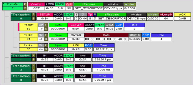
Figure 7. This is Figure 6 with the first transfer expanded to show packets and NAK handshakes.
For clarity, the Figure 6 trace suppresses NAK (Negative Acknowledge) handshakes sent back by the MAX3420E. Figure 7 expands the first transfer to the packet level to show a bit more detail. Now you see that Transfer 0 begins with three packets:
- The host sends a SETUP packet (63) addressed to the just-connected device (USB sends address 0 for this situation).
- The host sends a DATA packet (64) containing an 8-byte "op-code."
- The peripheral (the MAX3420E) sends back an ACK packet (65) to acknowledge error-free receipt of the two host packets.
If you turn on your system containing the MAX3420E, plug into USB, and set CONNECT = 1 (but nothing more), you will see the MAX3420E providing the ACK handshake (packet 65 in step 3 above). The MAX3420E hardware automatically acknowledges the SETUP stage of a CONTROL transfer, as mandated by the USB Specification.
Next, the host starts sending IN requests starting with Transaction 1. Each IN request is greeted by the NAK (Negative Acknowledge) handshake from the MAX3420E. This is because the program is not running and, therefore, the microcontroller attached to the MAX3420E never sees the SUDAV IRQ (Setup Data Available Interrupt Request).
Note: the MAX3420E alerts the microcontroller that a SETUP packet arrived by asserting the SUDAV IRQ. This informs the microcontroller that it needs to decode the packet data and respond by sending back the requested data.
These IN-NAKs go on for 5.687s, at which time the PC resets the bus and starts its second try. The little blips you see in Figure 4 are the IN-NAKs. If you watch the scope closely, you will see the pattern change slightly after about 5s—this is the bus reset (about 30ms of both D+ and D- low) followed by another SETUP packet. Then the IN-NAKs continue for another 5s.
FYI: Another Analyzer

Figure 8. The Beagle.
You may not have the budget for a USB bus analyzer like the one that produced Figure 6 and Figure 7. Although this application note assumes that you only have a scope and Ohmmeter, we strongly advise that you get a USB bus analyzer for your USB development work. The LeCroy/CATC that we used has the advantage of a beautiful interface, lots of software, and, most importantly, the reputation as the industry-standard USB measurement tool. Many arguments (hardware, software, chip, etc.) have been settled by exchanging CATC traces to prove exactly what is going on. The bus does not lie.
Fortunately, low-cost USB analyzers also are available. Figure 8 is a screen shot from the Beagle-USB. The Beagle analyzer shows bus traffic at a fraction of the LeCroy/CATC price. If you compare Index 10 in Figure 8 with Packet 64 in Figure 6, you will see that they display exactly the same data in the SETUP packet.
Checking Your Progress
If you see the signals in Figure 4, you have verified that the USB connector is wired correctly and that the MAX3420E is correctly powered. If you do not get this far, here are a few things to try:
- Probe the MAX3420E RES# pin and verify that it is HIGH.
- Probe the crystal and insure that it is oscillating at 12MHz. It must be 12MHz ±0.25% to meet the USB specification. If it is out of tolerance, make sure that you have the correct load capacitors as specified for the parallel resonant crystal (18pF is a common value).
- Check VCC for 3.3V.
- Check VL for your system interface voltage. Make sure this is not higher than 3.6V.
- If you are powering the MAX3420E VCC pin from VBUS by a 3.3V regulator, make sure that you are connected to USB. Otherwise, the MAX3420E is getting no power on VCC.
Note: It is easier to debug a self-powered design than a bus-powered design, since the firmware runs whether or not the USB cable is attached. It is a good idea to power your prototype using an external supply. If necessary, you can convert it to bus power later.
The next step verifies that your controller is successfully talking to the MAX3420E register set over the SPI bus.
Verify rreg() and wreg().
Any code you write, whether you use Maxim's example code or start from the beginning on your own requires functions to read and write the MAX3420E registers. The examples below use these function prototypes:
unsigned char rreg(BYTE r);   // Read a MAX3420E register byte
void wreg(BYTE r,BYTE v);     // Write a MAX3420E register byte
Before attacking code that services USB transfers, write a simple routine to test these functions. See Figure 9 as an example:

Figure 9. Single-step and examine 'rd' eight times to verify the SPI interface to the MAX3420E.
The test code in Figure 9 resets the MAX3420E, and then writes eight bytes consisting of a walking-one pattern to the USBIEN register. Each byte has one bit set, starting with 00000001, then 00000010, and ending with 10000000. Single-step through this function and inspect the value of "rd" eight times, confirming that they are 0x01, 0x02, 0x04, 0x08, 0x10, 0x20, 0x40 and 0x80. If so, you confirmed both register write and read operations over the SPI interface. If you can write the USBIEN register and reliably read back its contents, you can write and read all MAX3420E registers.

Figure 10. Single-stepping and inspecting a variable's value using Rowley CrossStudio for the MAXQ2000 microcontroller. Place the cursor over 'rd' and its value pops up.
Figure 10 is a screen shot of a debug session using CrossStudio. for the MAXQ2000 microcontroller. The popup window is activated by placing the cursor over the "rd" variable. (The screen shot does not display the cursor.) Any variable can be inspected this way while single-stepping through the code.
The test code begins by setting up the microprocessor SPI port. The SPI_Init() function will vary for each microprocessor type and specific IO pin assignments. Then the code sets up the MAX3420E SPI interface for full-duplex operation by writing the PINCTL register with the value 0x10. This sets the FDUPSPI bit. The code then puts the MAX3420E into a known state by asserting the CHIPRES bit and then deasserting it. It is advisable to include a chip reset at the beginning of the code to put the MAX3420E into a known state at the beginning of every debug cycle.
If the code in Figure 10 does not produce the correct result, you should inspect the SPI signals to verify their operation.

Figure 11. Executing the first wreg() call.
The first call to wreg() in the test program, test_SPI(), writes MAX3420E register 17 with the value 0x10. The SPI bus traces should look like those in Figure 11.
Note: The traces shown in Figure 11 use SPI mode (0,0), where the SPI data is sampled on the rising edge of SCLK, and the quiescent SCLK level is low. Your trace may have different pulse durations, depending on the SPI interface, but the values shown at the SCLK rising edges should be the same.
The first byte of every SPI access is a command byte that follows the format shown in Figure 12. Looking at the Figure 11 MOSI trace during the first SLCK rising edges, we see the bit pattern 10001010, indicating register 17 (bits 7-3 are 10001, the value 17). Also, bit 1 is high, indicating a write operation. The second byte shows the bit pattern 00010000. This is the data written to register 17, which is 0x10 (only bit 4, the FDUPSPI register bit, is set). Therefore this SPI access writes register 17 with 0x10, which sets the FDUPSPI bit.

Figure 12. The MAX3420E command byte format.
An easy way to capture these traces is to set the scope or logic analyzer to trigger on the falling edge of SS#, then single-step through the wreg() calls.

Figure 13. First write to USBIEN register (test_SPI() function).
The next statement in test_SPI() checks the rreg() function. The first time through the loop the value 0x01 is written to the USBIEN register, as seen in Figure 13.

Figure 14. First call to rreg() function.
The test_SPI() function then reads back the value of the USBIEN register, which for the first pass through the loop should be equal to 1 (Figure 14). Each time through the loop the written and read-back bits should move one SCLK edge to the left.
After the MAX3420E register writes and reads are verified, the code can be debugged further. All checkout steps up to this point have been in the 'sanity check' category. Now we take the first step into actually handling USB traffic: we respond to the various MAX3420E interrupt request bits signaling that processor attention is required.
Initial IRQ Bit Settings
It may seem logical that MAX3420E interrupt bits assert only after USB bus traffic starts. Actually, some IRQ bits assert when you power up the MAX3420E, and others assert when you plug in the USB cable and when you set CONNECT = 1. The following section gives an overview of what to expect during this startup sequence.
Out of RESET
When you take the MAX3420E out of reset, certain interrupt request bits assert, even if you are not yet connected to USB. These bits are:
EPIRQ Register:
- IN3BAVIRQ
- IN2BAVIRQ
- IN0BAVIRQ
The initial value of the EPIRQ register should be 0x19. The MAX3420E asserts these three IRQ bits to indicate that the three IN endpoint FIFOs are available for loading. BAV means 'Buffer Available.'
USBIRQ Register:
- OSCOKIRQ
The initial value of the USBIRQ register should be 0x01. When powered up, the MAX3420E starts its on-chip oscillator. After it stabilizes, the MAX3420E asserts the OSCOKIRQ bit to indicate that it is ready for operation. If your program hangs on the test checking for the OSCOKIRQ bit, make sure you have 3.3V on the VCC pin. VCC powers the oscillator.
Note: The MAX3420E IRQ register bits are active whether or not their associated enable bits (in the EPIEN and USBIEN registers) are set. The enable bits determine if the request bits get passed on to the logic driving the INT pin. See application note 3661, the MAX3420E Interrupt System, for more details.
After USB Plug-In
Additional USBIRQ bits assert when you plug into USB (with CONNECT = 0) even though there is no USB traffic. The EPIRQ bits remain the same as in the above section, but more USBIRQ bits may assert:
USBIRQ Register:
- OSCOKIRQ
- VBUSIRQ (maybe)
The VBUSIRQ bit indicates that the MAX3420E detected a plugged-in USB cable by sensing 5V on the VBCOMP pin. This assumes that you have wired the VBUS pin on the USB connector to the MAX3420E microcontroller (VBUS Comparator) input pin.
Note: Connecting the VBUS pin on the USB connector to the MAX3420E VBCOMP input pin is optional. The VBCOMP pin powers nothing inside the MAX3420E. It is routed only to the internal VBUS comparator.
After Setting CONNECT = 1
Connecting to USB causes the host to issue a bus reset, generate the Get_Descriptor-Device request, and eventually suspend the bus. These actions set additional IRQ bits in the USBIRQ Register. Note that the USB bus reset clears the VBUSIRQ bit.
EPIRQ Register:
- IN3BAVIRQ
- IN2BAVIRQ
- IN0BAVIRQ
- SUDAVIRQ (after traffic starts)
USBIRQ Register:
- OSCOKIRQ
- URESIRQ
- URESDNIRQ
- SUSPIRQ (eventually)
If you have VBUS connected to the VBCOMP pin, the USBIRQ register reads 0x8D for about 20s, and then 0x9D as the host suspends the bus.
What happens from here on will depend on your code. If you observe everything as stated above, you can continue to check out your code with good confidence that the system is in good order.
Debug Strategy: Activate Interrupts in 3 Steps
The remaining checkout makes sure that your firmware responds correctly to the various USB requests commanded by the PC, and thereby signaled by the MAX3420E. If you start your code, plug into USB, and nothing happens (perhaps with a Windows USB error message), it is likely that your program is missing interrupts. The following debug strategy can help troubleshoot interrupt problems.
Step 1: Poll the IRQ Bits
First write the code to directly poll the IRQ bits and to take processor action when the IRQs of interest are asserted. It is instructive to enable interrupts (individual IEN bits = 1 and IE = 1) even if your main program loop does direct polling. This is because you can observe the behavior of the MAX3420E INT pin to help understand its operation. This step effectively removes the microcontroller interrupt system (and code) from the checkout, allowing you to concentrate on achieving correct USB functionality. Do not worry about the wasted SPI cycles as you continuously read the EPIRQ and USBIRQ registers—the goal here is correct USB operation.
Step 2: Poll the INT Pin
Once correct USB operation is verified, take the second step of modifying the program to poll the MAX3420E INT pin to check for pending interrupts. If you verified your code in Step 1, you have a place in your code's main loop where you constantly read the EPIRQ and USBIRQ registers to check for pending interrupts. You can modify this continuous checking by inserting a statement that polls the microcontroller interrupt pin connected to the MAX3420E INT pin. If the MAX3420E INT pin is not asserted, you can skip over the statements that read the EPIRQ and USBIRQ registers. This simple check dramatically reduces the SPI traffic between the microcontroller and the MAX3420E, since the IRQ bits are tested only when asserted.
Step 3: Check Out Microcontroller Interrupt Code
As the third and final step, integrate the MAX3420E into the microprocessor's interrupt system. This usually involves writing an interrupt vector to automatically direct program execution to the MAX3420E handler.
Related to this Article
Products
Product Categories
{{modalTitle}}
{{modalDescription}}
{{dropdownTitle}}
- {{defaultSelectedText}} {{#each projectNames}}
- {{name}} {{/each}} {{#if newProjectText}}
-
{{newProjectText}}
{{/if}}
{{newProjectTitle}}
{{projectNameErrorText}}


