AD8479 Funnel Amplifier with Attenuation Factor of 60
Many applications demand differential measurements in the presence of large common-mode voltages, some upwards of a few hundred volts. Precision measurement at these voltages can be very difficult and expensive. However, the AD8479 is able to do so with ease. As mentioned in the AD8479 data sheet, the resistor network attenuates very large common-mode voltage down by a factor of 60 while providing a unity differential gain. There are, however, many applications that could benefit from a funnel amplifier that is able to withstand those very high voltages while measuring very large signals down to a more usable voltage domain. By leveraging the precision resistors in the AD8479, the built-in attenuation factor can be exploited to enable such a measurement.
Since the AD8479 attenuates a signal down by a factor of 60, the op amp inside the device must then amplify that differential signal by a factor of 60 to achieve unity differential gain. The gain is realized through the ratio of the resistors connected to the negative reference (Ref–) pin and to the output. Since the goal here is to achieve only attenuation, the gain can be bypassed by feeding the output signal back to the Ref– pin. In this configuration, unity gain is no longer attained, and a precision funnel amplifier is achieved. Since the AD8479 is in a fixed gain configuration, the amplifier is likely compensated appropriately and therefore may not be unity-gain stable. To maintain stability, one design requirement here was to ensure the amplifier is in its originally intended gain before the amplifier’s gain rolls off. The AD8479 data sheet lists the typical bandwidth as 310 kHz, therefore the negative reference feedback should be rolled off before this frequency. By connecting the AD8479 output through a low-pass filter, buffering the output of the filter, and routing the buffer output back to the negative reference pin, the AD8479 can be used as a very high voltage, precision funnel amplifier.

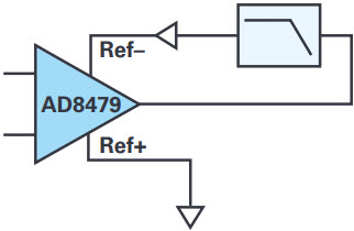
Figure 1. AD8479: Gain of 1/60 block diagram.
For a precision signal chain, keeping noise and offset to a minimum is important. In order to maintain this requirement, a buffer with low noise and low offset is desirable. The ADA4522 op amp in a unity-gain buffer configuration was selected for these reasons, along with its wide supply range. This enables the ADA4522 to be powered by the same supplies as the AD8479, which reduces complexity. One trade-off to using the ADA4522 is the overall circuit output voltage range since the input voltage range of the ADA4522 is 1.5 V from V+. Since the AD8479 and the ADA4522 have wide supply ranges, this trade-off can be mitigated by increasing the supply voltages if necessary. The input voltage range limit of the AD8479 is ±600 V, therefore the input voltage range of the ADA4522 will not limit the overall circuit range when using ±11.5 V or greater power supply voltages assuming a 0 V reference voltage.
For the low-pass filter, a single-pole RC filter will provide the desired result. It is also desirable to keep the low-pass filter resistor to a minimum to reduce its noise contribution for the same reason mentioned for the buffer. Also, too small of a resistor value would require a large filter capacitor for the same –3 dB frequency, which could exceed the capacitive load capability of the AD8479. As mentioned earlier, at dc, the gain is 1/60, and for stable operation, the gain at 300 kHz should be unity—therefore, since a single-pole RC filter is used, the roll off should occur at 5 kHz. For RC values, 10 nF and 3.16 kΩ were chosen since they meet the criteria above and they are also standard values.

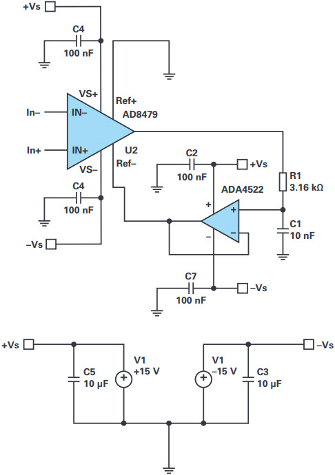
Figure 2. AD8479: Gain of 1/60 schematic.
As mentioned above, the –3 dB of the low-pass filter is 5 kHz. Since the buffer is supplying negative feedback for the op amp inside the AD8479, as the low-pass filter begins to roll off, the gain to the output of the AD8479 will increase for f > 5 kHz. Since the AD8479 output increases at 20 dB/decade once the low-pass filter starts rolling off, the resulting output of the filter and therefore the output of the buffer will be flat. Taking the system output at the buffer output will provide overall bandwidth limited only by the bandwidth and output range of the AD8479. This limitation is due to the increased gain to the AD8479 output for frequencies greater than 5 kHz, therefore this circuit has an input voltage range vs. frequency trade-off for frequencies at and above 5 kHz. For example, a 30 V p-p input at 150 kHz will have a –6 dB gain to the AD8479 output resulting in 15 V p-p, which is approaching the full-power bandwidth of the AD8479.

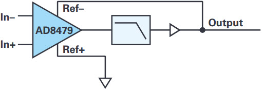
Figure 3. AD8479: Gain of 1/60 improved block diagram.
The oscilloscope capture in Figure 4 shows the result of the funnel amplifier configuration of the AD8479. The input signal is 100 Hz, 1200 V p-p, which is displayed as Channel 1 and is attenuated by a factor of 100 to avoid damaging the oscilloscope. Channel 2 is the output of the buffer amplifier and the results are exactly as desired. For a 1200 V p-p input, the funnel amplifier displays 20 V p-p.

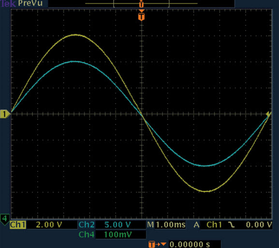
Figure 4. AD8479: Gain of 1/60 oscilloscope capture of input and output signals.
The oscilloscope capture in Figure 5 shows the results of the 30 V p-p, 100 kHz input signal. Just as in Figure 4, the funnel circuit provides the same attenuation of 1/60 at 100 kHz.

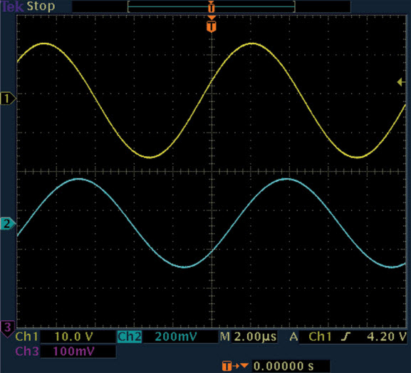
Figure 5. AD8479: Gain of 1/60 oscilloscope capture of input and output signals at 100 kHz.
Figure 6 displays the step response of the AD8479 funnel circuit. Driving the inputs with a 15 V p-p square wave results in a 250 mV p-p step response that is settled within a few microseconds.

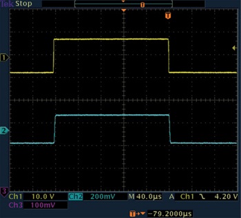
Figure 6. AD8479: Gain of 1/60 pulse response.
Since the AD8479 funnel amplifier configuration doesn’t gain up the differential signal as the standard AD8479 does, the noise is reduced. For the funnel amplifier configuration, the spectral noise density at 100 Hz is 27 nV/√Hz with 580 nV peak-to-peak voltage noise from 0.1 Hz to 10 Hz. As you can see, these noise values are approximately 1/60 of what is listed in the AD8479 data sheet, therefore the filter and buffer have a negligible effect on the noise. This is due to the fact that in a two-stage amplifier circuit the noise and offset of the second stage is divided down by the gain of the first stage. Since the gain from the AD8479 Ref– pin to the AD8479 output is –59, this (minus 1) is the factor by which the buffer noise and offset will be reduced.

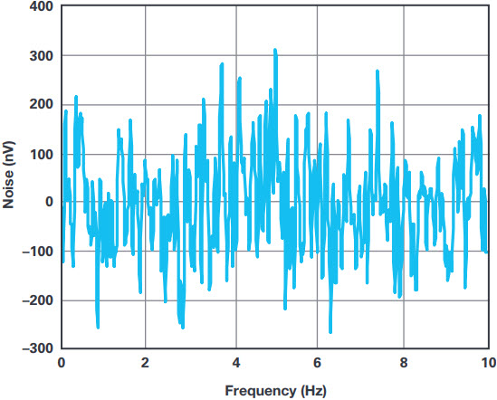
Figure 7. AD8479: Gain of 1/60 peak-to-peak noise (nV) 0.1 Hz to 10 Hz.
Two of the key specification of the AD8479 are the offset voltage and the common-mode rejection ratio. Since the noise gain of the AD8479 is now approximately 1 at dc, the offset from the op amp inside the AD8479 will be 1/60th of the offset specified in the AD8479 data sheet, which is ±1 mV for the B-grade model. The offset of the buffer is actually divided down by 60 due to the dc gain from the Ref– of the AD8479 to its output therefore the offset of the AD8479 itself is the main contributor of offset. The resulting maximum offset of this circuit is ±17 µV. Likewise, since the AD8479 op amp is no longer in a dc noise gain of 60, the CMRR errors from the AD8479 are also not gained up by 60. Since CMRR is the ratio of common-mode gain to differential gain and both of these quantities are reduced by a factor of 60, the resulting CMRR will be the same for the AD8479 funnel amplifier circuit, which is 90 dB for the B-grade model.
One application would be measuring voltage and current for an ac electric motor. Since ac lines are hundreds of voltages, performing accurate current and voltage monitoring can be difficult. Since the AD8479 is capable of working at these voltages, the current can be measured through the motor using a shunt resistor. Using the circuit described above, the voltage across the motor can be directly measured, therefore achieving an accurate power monitor solution with minimal effort.

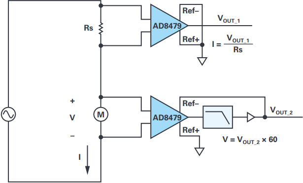
Figure 8. AD8479: Gain of 1/60 high voltage impedance measurement.
Although the AD8479 is a fixed unity-gain amplifier, a precision funnel amplifier can still be achieved. The funnel amplifier can be used for many applications, including supplementing a high voltage current measurement with the associated voltage across the load. Although the bandwidth of the funnel amplifier limits the input voltage range, typical line frequencies are well within the input voltage limiting frequencies, therefore the circuit performance is ideal for these types of measurements.
About the Authors
Related to this Article
Product Categories
{{modalTitle}}
{{modalDescription}}
{{dropdownTitle}}
- {{defaultSelectedText}} {{#each projectNames}}
- {{name}} {{/each}} {{#if newProjectText}}
-
 {{newProjectText}}
{{/if}}
{{newProjectText}}
{{/if}}
{{newProjectTitle}}
{{projectNameErrorText}}
Latest Media 21


