Accurate High-Side Current-Sense Amplifier Monitors PWM Load Current
Abstract
Accurate high-side current sensing is essential for automotive control systems such as electric power steering, automatic gear shifting, transmission control, engine fuel-injection control, valve control in braking, and active suspensions. All of these applications require precise regulation of the current through a motor or solenoid, to control either the torque of the motor or the drive of the solenoid. The circuit presented in this article includes a precision, high-side current-sense amplifier (MAX9918) for monitoring inductive load currents over a wide range of input common-mode voltages. It is suitable for applications in which the input common voltage can become negative due to inductive kick-back, reverse-battery conditions, or transient events.
A version of this application note was published March 3, 2011 on www.edn.com.
Current Sensing in an Electric Power Steering (EPS) System
Unlike conventional power-steering systems, an EPS system does not include a hydraulic pump or fluid. Instead, it features an electric motor attached to the steering rack via a gear mechanism. When the driver turns the wheel, a steering sensor detects the wheel’s position and rate of rotation. This information is fed to the power-steering control module, along with input from a steering torque sensor mounted in the steering shaft. To determine the steering assist needed, the control module also takes inputs from the vehicle speed sensor, traction control, and stability control systems (Figure 1).
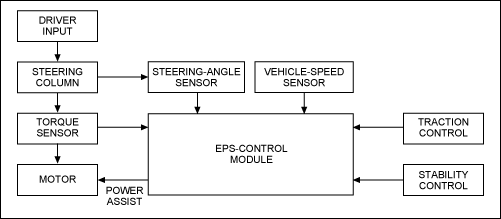
Figure 1. Simplified block diagram of a typical EPS system.
An interface with the power module then allows the control module to regulate the amount of current in the motor. Increasing the motor current increases the power assist, and vice versa. Motor current is usually controlled by feeding a pulse-width modulated (PWM) voltage across the motor using an H-bridge circuit (Figure 2). An associated truth table (Table 1) summarizes the various modes of operation for a full H-bridge circuit. The motor presents an inductive load, so torque is determined by averaging the resulting ripple current—that is, the resulting power assist provided to the driver.
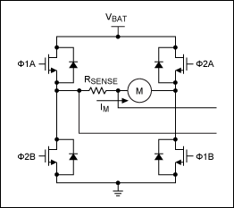
Figure 2. The phase of signals to the four gates of this H-bridge circuit determines motor direction and speed.
| Φ1A | Φ1B | Φ2A | Φ2B | Condition |
| ON | ON | OFF | OFF | The motor is powered between VBAT and ground and its current IM increases and flows as indicated by the arrow. |
| OFF | ON | OFF | ON | The current IM flows as shown by the arrow, but decreases and circulates through Φ1B, Φ2B, and the sense resistor. |
| OFF | OFF | ON | ON | The motor is powered between VBAT and ground, and its current IM increases and flows in a direction opposite to the arrow. |
| OFF | ON | OFF | ON | The current IM flows in a direction opposite to the arrow. It also decreases and circulates through Φ2B, Φ1B, and the sense resistor. |
The current-measuring device monitors motor current and provides real-time feedback to the control module, allowing that module to adjust the PWM duty cycle until the current reaches its target value. A popular method for measuring motor current is to insert a low-valued sense resistor in series with the current path, which produces a small voltage drop. That differential voltage is amplified by a current-sense amplifier to indicate the current magnitude.
Three options are available for current sensing: low side, high side, and on the motor. Accordingly, you can place the sense resistor between the H-bridge and ground (low-side current sensing), on the bottom of the DC bus or between the positive battery terminal and H-bridge (high-side current sensing), or on the high-side of the DC bus or the motor itself (output motor PWM current sensing). These alternatives require different trade-offs. The low-side approach is convenient but adds undesirable resistance in the ground path, and it lacks the diagnostic ability to detect a short-to-ground fault. Neither the high-side nor the low-side approach let you monitor current in the recirculation diode continuously. PWM current sensing, however, is free of these drawbacks.
A PWM current-measuring circuit may seem simple, but it entails performance constraints that are far from trivial. The circuit must contend with common-mode voltages that swing all the way from ground to the battery voltage. Thus, to reject common-mode excursions, the circuit must have not only a high range of input voltage corresponding to this swing, but also an excellent CMRR at the switching frequency and at relevant frequencies induced by the edge rate.
Common-mode transients and a minimum duty cycle for the PWM signal also impose a stringent requirement for settling time in the current-sense amplifier. For an accurate and linear response, the current-measurement circuitry must have high gain, high accuracy, and low offset voltage. And because human intervention is part of the control loop, linearity and accuracy are especially critical. Any nonlinearity in the circuitry can impair the driving experience by causing oscillation or vibration when the vehicle is over-steered.
In the motor-current control and measurement circuit of Figure 3, the motor is connected in a full H-bridge configuration, which—because the applied voltage polarity is easily reversed—enables it to rotate in either direction. The IC shown withstands common mode voltages from -20V to +75V, making it immune to inductive fly-back, load dump transients, and reverse battery faults. The device also integrates an instrumentation amplifier, whose patented, indirect current-feedback architecture provides precision current sensing with an input offset voltage of 400µV (max) and a gain error of 0.6% (max). The external reference voltage supports bidirectional current sensing as required in a full H-bridge, and also unidirectional current sensing when operating with a half H-bridge circuit. In the bidirectional application, output voltage equals the reference voltage when the sensed current is zero. Both adjustable gain and fixed-gain flavors enable this part to provide maximum flexibility over a range of applications.
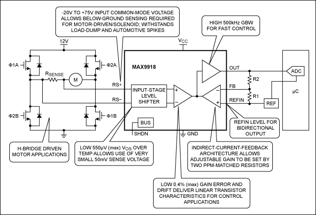
Figure 3. A PWM-compatible, H-bridge current-sensing circuit.
Current Sensing for Solenoid Drive
Solenoids are widely used as electromechanical switches in vehicles. A starter solenoid, for example, delivers a large electric current to the starter motor, which in turn sets the engine in motion. Several automotive control systems, however, employ a solenoid drive for precision control. For example, a common diesel engine system for railroads relies on solenoids as sophisticated electronic control valves, which inject the right quantities of fuel directly into the individual engine cylinders at high pressure. The timing of these valves is accurately controlled by the engine control unit to ensure synchronism with the diesel engine. The result is a relatively "green" engine that makes less noise, produces fewer emissions, and is more fuel efficient. Other applications for solenoid control include automatic gear shifting, transmission control, braking control, and active suspensions.
The high-side switch is typically an FET whose gate is controlled by a PWM signal (Figure 4). When the FET is ON, it connects the solenoid to the 14V battery voltage, producing a current that charges the solenoid coil. When the FET turns OFF, solenoid current discharges through the clamp diode and shunt resistor. Regulation of the PWM frequency and duty cycle determines the resulting average ripple current in the solenoid, which in turn controls the force applied to the actuator.
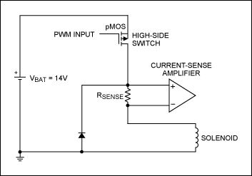
Figure 4. This typical solenoid drive circuit employs a high-side shunt.
The challenges of sensing solenoid current for the purpose of regulating PWM frequency and duty cycle are similar to those found in the H-bridge application. Common-mode voltages at the input of the current-sense amplifier range from the battery voltage down to the slightly negative level of the clamp diode’s drop voltage. Typical solenoids require a few amperes of current, so a clamp diode that withstands such current may develop a forward voltage higher than 1V.
Again, the current-sense amplifier’s wide input common-mode range and fast settling in response to common-mode variations are well suited to this application. The main difference between this application and that of the H-bridge is that the solenoid current always flows in the same direction, and therefore the current-sense amplifier need only be unidirectional. (The MAX9918 becomes a unidirectional current-sense amplifier when you connect its reference input (REFIN) to ground.)
Lab Results
Figure 5 shows a typical application circuit for solenoids as prototyped in the lab. The solenoid is emulated by a 2mH inductor, with low ESR of 1.6Ω. The sense resistor is 100mΩ, and an R4 value of 15Ω limits the maximum solenoid current to:
IMAX = VBAT/(RSENSE + ESR + R4) = 12V/(0.1 + 1.6 + 15)Ω = 0.72A
(Note that R4 is not present in an actual solenoid circuit.)
This maximum current value is the theoretical limit reached when the inductor is fully charged. The resistor and inductor values shown set the circuit time constant to about 0.12ms, which is equivalent to approximately 8.3kHz. A gain of 80 is set by the external resistors R1 = 1kΩ and R2 = 79kΩ.
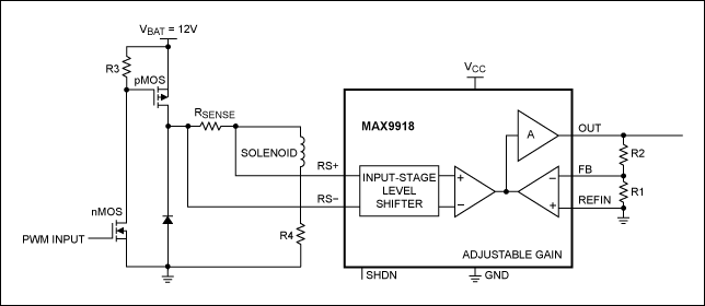
Figure 5. This solenoid drive circuit was prototyped in the lab.
Operation of the Figure 5 circuit is illustrated by waveforms at a PWM frequency of 5kHz, with duty cycles of 80% (Figure 6) and 50% (Figure 7). The top waveform is voltage across R4, which is proportional to current flowing in the inductor. The middle waveform is the output of the current-sense amplifier, and the bottom waveform shows the PWM signal at the drain of the PFET. Higher duty cycles yield higher current, as one expects.
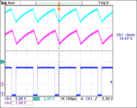
Figure 6. Waveforms from Figure 5, with 5kHz PWM frequency and 80% duty cycle. (Top trace is the voltage across R4, middle is the output of the current-sense amplifier, and bottom is PWM signal at the bottom of the pFET.)
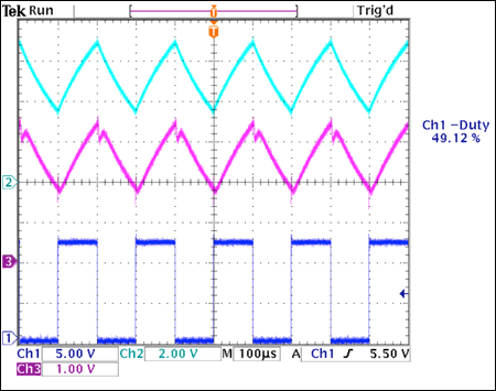
Figure 7. Waveforms from Figure 5, with 5kHz PWM frequency and 50% duty cycle. (Top trace is the voltage across R4, middle is the output of the current-sense amplifier, and bottom is PWM signal at the bottom of the pFET.)
Thus, a precision high-voltage, high-side current-sense amplifier such as the MAX9918 allows accurate measurement with smaller sense resistors. It handles the bidirectional motor currents derived from H bridges, like those found in EPS systems, as well as the unidirectional solenoid currents found in automatic gear shifting, transmission control, braking control, and active suspensions.
Related to this Article
Products
PRODUCTION
-20V to +75V Input Range, Precision Uni-/Bidirectional, Current-Sense ...
PRODUCTION
-20V to +75V Input Range, Precision Uni-/Bidirectional, Current-Sense ...
PRODUCTION
-20V to +75V Input Range, Precision Uni-/Bidirectional, Current-Sense ...
{{modalTitle}}
{{modalDescription}}
{{dropdownTitle}}
- {{defaultSelectedText}} {{#each projectNames}}
- {{name}} {{/each}} {{#if newProjectText}}
-
{{newProjectText}}
{{/if}}
{{newProjectTitle}}
{{projectNameErrorText}}


