With this reference design and firmware, IO-Link allows the user to program and diagnose a four-channel industrial
analog output peripheral module (MAX22007PMB#). This enables industrial actuator or sensor equipment original
equipment manufacturers (OEMs) to provide end-users with total flexibility at the factory floor level to simplify
equipment installation and commissioning, while reducing their own number of stock keeping units, reducing their
bill of materials (BOMs), and simplifying and streamlining their own purchasing and manufacturing.
The demonstration firmware provides an example of how to use the MAXREFDES284# with the MAX22007PMB#. The
demonstration supports 1-byte PDIn and 7-byte PDOut, where the PDIn data is used as an 8-bit message counter,
the 7-byte PDOut is split into 4x 12-bit digital-to-analog converter (DAC) values, one for each analog output, and 1
byte to switch the display through different modes, that is, application data display, timing analysis vs. cycle-time
measurements. The minimum cycle-time is defined by the process-data length and COM rate, and with this mode
800μs cycle-time can be reached. The MAX22007PMB# demonstrates four industrial analog outputs that can be
individually configured between voltage mode (0V to12.5V) or current mode (0mA to 25mA).
Built in an industrial form factor, and measuring just 75mm x 33mm, the MAXREFDES284# uses an industry-standard M12 connector, allowing a 4-wire IO-Link cable to be used. On the other side, a 12-pin peripheral module can
be connected. A 2-pin terminal block provides external access to the 24V that is delivered from the IO-Link master,
providing up to 24W.
The demonstration application comes with matching input/output device descriptor (IODD) files, supporting
multiple parameters.
In this reference design, a MAX32660 low power microcontroller interfaces between the MAX22516 and peripheral
module connector. The MAX22516 features an integrated data link controller that allows the device to
autonomously respond to process-data requests from the IO-Link Master as well as manage indexed service data
unit (ISDU) transfers, offloading all time-critical tasks from the microcontroller.
The microcontroller can update and read the PDIn and PDOut data at any time. The indexed service data unit
(ISDU) requests are stored in a separate buffer and, consequently, are handled without interrupting application
tasks. The MAX22516 also integrates surge protection for robust communication without requiring external
protection components such as TVS diodes. The MAX22516 is available in a form factor friendly 3.53mm × 3.16mm,
42-bump wafer level packaging (WLP) as well as a 40-pin TQFN package, allowing the MAXREFDES284# to have a
small footprint. The reference design is reverse-polarity protected using the integrated active reverse-polarity
protection of the MAX22516. The MAX22516 has an integrated DC-DC converter as well as two integrated linear
regulators (3.3V and 5.0V). The DC-DC converter is used to generate the 3.3V supply for the microcontroller,
reducing power dissipation as well as the number of external components required, further saving additional space
on the board. The MAX22516 also features a low on-resistance C/Q driver to reduce power dissipation, allowing this
reference design to consume minimal power with very low thermal dissipation.
This IO-Link device was tested to IO-Link Standard 1.1.3 using the TEConcept Device Tester. Connecting the
MAXREFDES284# to a USB IO-Link master, such as the MAXREFDES165# or MAXREFDES145#, with the associated
software allows for easy evaluation.
Advanced factory automation solutions (that is, Industry 4.0) require an increasing number of smart sensors and smart actuators, which are typically controlled using IO-Link® point-to-point serial communication between the sensor/actuator and IO-Link master. As a leading provider of IO-Link device transceiver and master transceiver ICs, Analog Devices, Inc., also provides complete reference design solutions to help our customers improve their time to market. These proven designs cover all the hardware and software requirements needed for compliance with the IO-Link standard.
IO-Link is the first open, field bus agnostic, low-cost, point-to-point serial communication protocol used for communicating with sensors and actuators that has been adopted as an international standard (IEC 61131-9). IOLink standardizes interoperability of industrial equipment from all over the world. IO-Link can function directly from a PLC or be integrated into standard field buses, quickly making it the de-facto standard for universally communicating with smart devices like the MAXREFDES284#.
The MAXREFDES284# is a complete, IO-Link reference design that allows an engineer to connect device or actuator development boards with a Pmod™-compatible peripheral module connector, and interface to an IO-Link Master. The MAXREFDES284# consists of a MAX22516 IO-Link transceiver with integrated data link controller and protection, a microcontroller to run application code, and has a peripheral module connector to connect device or actuator functions, supporting SPI, I2, or UART interfaces.
The complete reference design fits on a 75mm x 33mm printed circuit board (PCB). Design files and software are available on the Design Files folder. The board is also available for purchase.
Figure 1. MAXREFDES284# IO-Link to Peripheral Module Device.
Features
IEC 61131-9-Compliant
IO-Link Version 1.1-Compliant
Applications
Industrial Automation
Actuator Modules
Programmable Logic Controller (PLC) Systems and Distributed Controller Systems (DCS)
With this reference design and firmware, IO-Link allows the user to program and diagnose a four-channel industrial
analog output peripheral module (MAX22007PMB#). This enables industrial actuator or sensor equipment original
equipment manufacturers (OEMs) to provide end-users with total flexibility at the factory floor level to simplify
equipment installation and commissioning, while reducing their own number of stock keeping units, reducing their
bill of materials (BOMs), and simplifying and streamlining their own purchasing and manufacturing.
The demonstration firmware provides an example of how to use the MAXREFDES284# with the MAX22007PMB#. The
demonstration supports 1-byte PDIn and 7-byte PDOut, where the PDIn data is used as an 8-bit message counter,
the 7-byte PDOut is split into 4x 12-bit digital-to-analog converter (DAC) values, one for each analog output, and 1
byte to switch the display through different modes, that is, application data display, timing analysis vs. cycle-time
measurements. The minimum cycle-time is defined by the process-data length and COM rate, and with this mode
800μs cycle-time can be reached. The MAX22007PMB# demonstrates four industrial analog outputs that can be
individually configured between voltage mode (0V to12.5V) or current mode (0mA to 25mA).
Built in an industrial form factor, and measuring just 75mm × 33mm, the MAXREFDES284# uses an industry-standard M12 connector, allowing a 4-wire IO-Link cable to be used. On the other side, a 12-pin peripheral module can
be connected. A 2-pin terminal block provides external access to the 24V that is delivered from the IO-Link master,
providing up to 24W.
The demonstration application comes with matching input/output device descriptor (IODD) files, supporting
multiple parameters.
In this reference design, a MAX32660 low power microcontroller interfaces between the MAX22516 and peripheral
module connector. The MAX22516 features an integrated data link controller that allows the device to
autonomously respond to process-data requests from the IO-Link Master as well as manage indexed service data
unit (ISDU) transfers, offloading all time-critical tasks from the microcontroller.
The microcontroller can update and read the PDIn and PDOut data at any time. The indexed service data unit
(ISDU) requests are stored in a separate buffer and, consequently, are handled without interrupting application
tasks. The MAX22516 also integrates surge protection for robust communication without requiring external
protection components such as TVS diodes. The MAX22516 is available in a form factor friendly 3.53mm × 3.16mm,
42-bump wafer level packaging (WLP) as well as a 40-pin TQFN package, allowing the MAXREFDES284# to have a
small footprint. The reference design is reverse-polarity protected using the integrated active reverse-polarity
protection of the MAX22516. The MAX22516 has an integrated DC-DC converter as well as two integrated linear
regulators (3.3V and 5.0V). The DC-DC converter is used to generate the 3.3V supply for the microcontroller,
reducing power dissipation as well as the number of external components required, further saving additional space
on the board. The MAX22516 also features a low on-resistance C/Q driver to reduce power dissipation, allowing this
reference design to consume minimal power with very low thermal dissipation.
This IO-Link device was tested to IO-Link Standard 1.1.3 using the TEConcept Device Tester. Connecting the
MAXREFDES284# to a USB IO-Link master, such as the MAXREFDES165# or MAXREFDES145#, with the associated
software allows for easy evaluation.
The MAXREFDES284# IO-Link to peripheral module device uses minimal power, space, and minimizes cost, making it a complete solution for many sensors and actuators found in various industrial control and automation applications.
The MAX22516 IO-Link device transceiver is compliant with the IO-Link version 1.1/1.0 physical layer specification. It integrates the high-voltage functions commonly found in industrial sensors and actuators, including drivers, DC-DC converter, and two linear regulators. The MAX22516 features extensive integrated protection to ensure robust communication in harsh industrial environments. All three I/O pins (V24, C/Q, and GND) on the MAX22516 are reverse-voltage and short-circuit protected and feature integrated ±1kV/500Ω surge protection. This enables a very small PCB area with no external protection components required. The low on-resistance driver (C/Q) further reduces power dissipation. So, this reference design consumes minimal power with very low thermal dissipation. Operation is specified for normal 24V supply voltages up to 36V. External transient protection is simplified due to the high voltage tolerance (that is, 65V absolute maximum rating) for the I/O pins in addition to the integrated surge protection.
The integrated DC-DC regulator in the MAX22516 generates the 3.3V supply for the microcontroller, reducing the number of additional external components and required space.
An additional MAXM17761 DC-DC converter module on the PCB provides 3.3V to the Pmod style connector, allowing currents of up to 1A for the connected peripheral module.
The MAX22516 features an integrated data link controller that significantly simplifies the IO-Link communication timing requirements with independent buffers for PDIn, PDOut, and ISDU transfers. The microcontroller can read or write to/from the buffers as the application allows, independent from the IO-Link Master timing.
Detailed Description of Firmware
The MAXREFDES284# ships preprogrammed as a working IO-Link device ready to connect to an IO-Link master. The firmware configures and controls a peripheral module. After plug-in, the MAXREFDES284# waits for a wake-up signal from the IO-Link master. Once the wake-up signal is received, the MAXREFDES284# synchronizes with the IOLink master using the 230.4kbps (COM3) baud rate, and communication parameters are exchanged. The IO-Link master then starts a cyclic data exchange by transferring the process data. If the MAXREFDES284# is removed, the IO-Link master detects a missing device. This reference design uses the TE-Concept IO-Link stack and the stack-library provided with the demo-project is for evaluation only. The full version of the stack can be purchased at TE-Concept.
The MAXREFDES145# is an eight-port IO-Link Master utilizing the TEConcept IO-Link Master Stack. The TEConcept IO-Link Control Tool software is Microsoft Windows®-compatible and features input output device description (IODD) file import capability, automatic download from IODD Finder, connects to a PC through USB, and is available to download from the Analog Devices website.
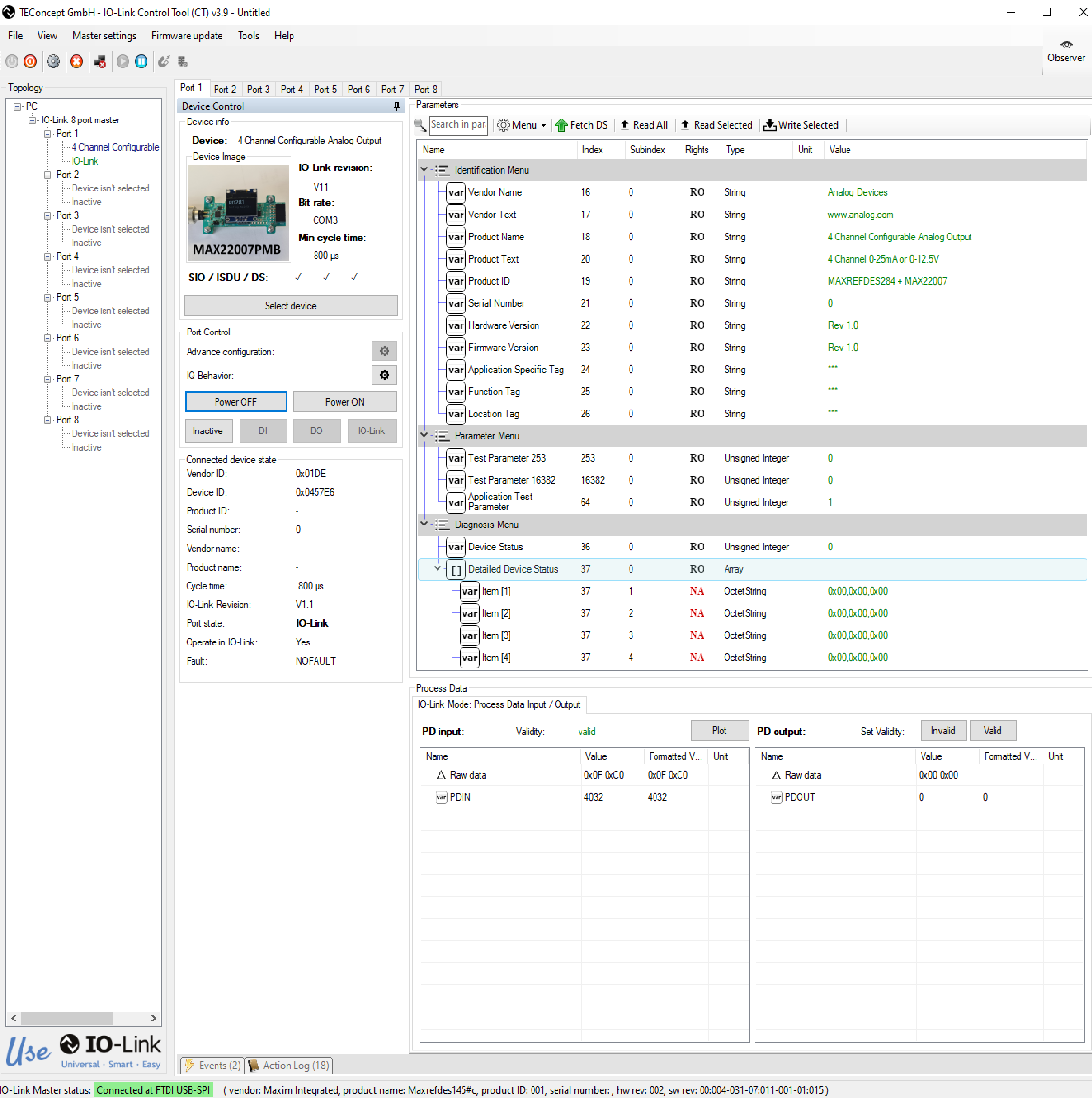
Figure 4 shows the TEConcept IO-Link Control Tool software.
The MAXREFDES284# was verified using the MAXREFDES145# IO-Link Master, featuring the MAX14819 IO-Link master transceiver and the IO-Link Control Tool from TEConcept.
Download the IODD file (*.xml) located in the Design Files folder and follow the step-by-step instructions in the Quick Start Guide section on how to use the software. Figure 4 shows a screenshot of the TEConcept IO-Link Control Tool communicating with the master and device.
Figure 4. TEConcept IO-Link Control Tool GUI.
Restrictions and Warnings for ADI Reference Design Use
The MAXREFDES284# is designed and tested to meet IO-Link operation and harsh industrial environments covered by IEC 61000-4-x standards for transient immunity. This board and associated software are designed to evaluate the performance of the MAX22516 but are not intended to be deployed as-is into an end product in a factory automation system.
The MAXREFDES284# is not for use in functional safety or safety-critical systems.
To test the MAXREFDES284#, connect it to a port of an IO-Link master. In the following example, a MAXREFDES145# IO-Link master and TEConcept IO-Link Control Tool are used, but any IO-Link-compliant master and associated IOLink device GUI should work.
Required Equipment
MAXREFDES284#
MAXREFDES284 IODD File
IO-Link Master with 24V AC-to-DC Power Adapter (example, MAXREFDES145#)
TEConcept IO-Link Control Tool Software
IO-Link Cable
Windows PC with USB 2.0 Type A-to-B Cable
Master Setup Procedure
Connect the MAXREFDES284# to the IO-Link master with an IO-Link M12 cable.
Connect the IO-Link master to the PC with a USB cable.
Download and install the latest IO-Link Control Tool software from the Analog Devices website.
Download the IODD file for the MAXREFDES284# either from the Design Files folder or from the IODD Finder website.
The MAXREFDES284# comes preprogrammed with firmware that supports MAX22007PMB# Mode.
MAXREFDES284# Testing Procedure
The MAXREFDES284# supports four-channel analog output using the MAX22007PMB#. To use this option, connect the MAX22007PMB# to MAXREFDES284# before providing 24V from the IO-Link master.
Testing Procedure (Four Channel Analog Output Using MAX22007PMB#)
Connect the female end of the IO-Link cable to the MAXREFDES284# (see Figure 3).
Connect the male end of the IO-Link cable to one of the ports on the IO-Link master. In this example, use the MAXREFDES145# as the IO-Link master.
Make sure that the MAXREFDES145# is powered with 24V supply and connected to the PC through a USB cable.
Open the IO-Link Control Tool software and press ‘Refresh’ under FTDI USB-SPI. The GUI automatically finds the IO-Link master. Click the green ‘Connect’ button (Figure 5).
Figure 5. IO-Link Control Tool Connect.
Click ‘Select Device’ to open the window to load the IODD file (Figure 6).
Figure 6. Select Device on IO-Link Control Tool GUI.
Import the IODD file (MAXIM-RD284_MAX22007PMB_COM3) for the MAXREFDES284#. The TE-Concept GUI also allows to automatically download the IODD file from the IODD Finder by clicking ‘IODD Finder’ in the ‘Select Device’ menu (Figure 7).
Figure 7. Import the IODD File on IO-Link Control Tool.
In the ‘Device Tree’ on the left side, select the ‘Port’ where the MAXREFDES284# is connected to (Figure 8).
Figure 8. ‘Power On’ Port in IO-Link Control Tool.
Click ‘Power ON’ to enable the L+ supply for the selected ‘Port’. The power-led on MAXREFDES284# as well as the red L+ LED on the selected MAXREFDES145# ‘Port’ should now be on.
Then, click ‘IO-Link’ (Figure 9).
Figure 9. IO-Link Control Tool (IO-Link Communication Connected).
If communication is established correctly, the IO-Link Control Tool software shows the ‘Vendor ID’, ‘Device ID’, ‘Cycle time’, as well as the ‘Process Data input (PD input)’ (Figure 9). Next to ‘PD input’, it should show ‘Validity: valid’ in green. This means the master is successfully communicating with the IO-Link device.
If the MAX22007PMB# is connected at power-up:
The MAXREFDES145# automatically detects this and opens the appropriate IODD (Figure 10).
Figure 10. MAX22007PMB# Connected at Power-Up (IODD Automatically Setected).
The PDin shows an 8-bit message counter (Figure 11).
IO-Link master (that is, MAXREFDES145#) with a 24V AC-to-DC power adapter
IO-Link cable
MAXREFDES284#
MAX22007PMB
MAX32625PICO with associated ribbon cable to connect to SWD connector on MAXREFDES284# PCB
One USB 2.0 USB A-to-Micro-B cable
Microsoft Windows PC with one USB 2.0 type A-to-B cable
Software Required
TEConcept IO-Link Control Tool software
MAXREFDES284# IODD file
Eclipse MaximSDK
Eclipse MAXREFDES284 Project
Note that this eclipse project contains a demo application and an evaluation version of the IO-Link stack from TE-Concept.
The full version of this stack can be purchased from TE-Concept: www.teconcept.de
Setup Steps
Install the Eclipse MaximSDK. Install files can be downloaded from the Analog website here. Installation instructions are available here. See Figure 13.
Figure 13. Eclipse Loading Window.
Create a new workspace folder on the PC.
Copy the RD284_interfaces2 Eclipse project into the new workspace folder.
Open Eclipse MaximSDK.
Select the above workspace project, click, and Launch.
Importing Device Examples
The Maxim Arm® Cortex® Toolchain contains many examples demonstrating the features of the supported devices. Each device has its own set of examples and libraries that are separated into directories based on part numbers. Device directors are located on the C: drive at C:\Maxim\Firmware\<device>\Applications\EvKitExamples.
To begin working with the examples for the chosen device, complete the following steps.
Expand the ‘General’ folder and select ‘Existing Projects’ into ‘Workspace’. Click Next. The ‘Import Projects’ dialog box appears (Figure 15).
Figure 15. Import Projects Dialog Box.
Click Browse and select the folder containing the MAXREFDES284# examples to import. Select ‘Folder’.
The ‘Import Projects’ dialog box reappears showing the root directory selected and a list of device examples in the ‘Projects’ field.
Select the check box to the left of each device example to import.
Select the Copy projects into workspace check box.
Click Finish to import the device examples into the workspace folder.
Building a Project
This section describes the steps to build the imported device project for the MAXREFDES284#. See ‘Importing Device Examples’ for instructions about importing Eclipse sample projects into the workspace.
To build a project, complete the following steps:
Select Window > Show View > Project Explorer from the menu bar. The ‘Project Explorer’ tab appears on the Eclipse home page.
Select RD284_interfaces2 > Build Project using the hammer symbol above the ‘Project Explorer’ tab.
Select Window > Show View > Console. The results of the build appear on the ‘Console’ tab (Figure 16).
Figure 16. Eclipse Console Window.
Debugging a Project
Before debugging a project, make sure the MAXREFDES284# kit is properly connected and powered (Figure 17).
Figure 17. Hardware Setup.
To debug a project, complete the following steps.
Select Window > Show View > Project Explorer from the menu bar. The ‘Project Explorer’ tab appears on the Eclipse home page.
Select RD284_interfaces2 and right click with mouse, then select Debug As > Debug Configurations on the ‘Project Explorer’ tab. The Debug Configurations window appears (Figure 18).
Figure 18. Debug Configurations Window.
Select GDB OpenOCD Debugging > RD284_interfaces2 Default in the left navigation panel.
The right-hand panel reappears, showing the debug settings specific to the RD284_interfaces2 project.
Ensure Project: and C/C++ Application: are populated (Figure 19).
Click Debug. Eclipse opens the ‘Debug’ perspective and attempts to build the program loaded.
Load the program to the MAX32660 flash memory, as discussed in the next sections.
Code Explained (main.c)
This section provides a brief explanation of the code contained within the main.c file.
Headers and Pin Definitions
At the top of the main.c file are calls to various libraries (header files) that must be included in the program (Figure 21). These files contain code and macro definitions required to run the program.
Figure 21. Header Files Within main.c.
The mxc_ files are modules in the ‘MAX32660 Peripheral Driver API’ directly associated with the configuration of the MAX32660. Similarly, the spi_driver and I2_driver files are embedded SPI and I2 controller drivers for the MAX32660.
The oled_driver.h is the library for communicating with, and displaying information on, the OLED display.
Pin definitions are included as comments below the list of header files for clarity.
The main() function
Figure 22 shows the main function within the program.
Figure 22. Main Body Within main.c.
The code begins by initializing the interface and device parameters, then executes an infinite while loop of the primary functions and tasks. These functions are explained in more detail below.
Initialization Tasks
MXC_Delay(50000)
This function blocks further processing and generates a delay in microseconds. The delay is set to 50ms, in this case. This function call at the beginning of the program is used to ensure that the power is stable and the microcontroller is ready following power-up, before the device begins to operate.
I2_Init()
This function initializes the I2 interface. The I2 clock frequency is 400kHz. The I2 interface is primarily used with the OLED display.
MAX22007_init()
This function initializes the MAX22007PMB board by setting the SPI clock frequency to 10MHz. All GPIOs on the MAX22007PMB board are configured as outputs and are enabled. All LEDs are turned off.
stack_main()
This function initializes the IO-Link device stack, configures SIO mode, and sets level of the C/Q line of the MAX22516. This function also initializes values for the ‘Direct Parameter Page 1’ variables.
OLED_Init()
This function initializes the OLED display.
Operating Tasks
This infinite loop continuously cycles through the following functions.
application_main_loop()
See the ‘Code Explained (application.c)’ section.
parameter_cyclic()
This function processes background tasks including storing parameters to the electrically erasable programmable read-only memory (EEPROM) and reading/writing data for ISDU requests.
MAX22516_API_phy_cyclic()
This function ensure that the system state mode is synchronized with the DL state mode machine and must be called regularly to ensure normal operation.
How to Turn on the Red LED
Add the following line of code into main.c file before the while statement:
MAX22516_API_write_register(0x53,0x55);
Build the project: Click the hammer symbol in the toolbar at the top (Figure 23).
Figure 23. Build the Project.
Debug: Select pull-down on right-hand side of green bug symbol in the toolbar at the top (Figure 24). Select rd284 and click the small green triangle beside the vertical yellow bar to run (Figure 25).
Figure 24. Debug Mode Select.
Figure 25. Run the Project.
The red LED on PCB should now be flashing (Figure 26).
Figure 26. Red LED Location on MAXREFDES284#.
When finished, click the red square in the toolbar at the top to stop the program (Figure 27).
Figure 27. Stop the Program.
Click the C/C++ icon on the top right of the toolbar to return to the code (Figure 28).
Figure 28. Click the C/C++ Icon.
How to Turn on the Green LED
The process to turn on the green LED is very similar to turning on the red LED.
Add the following line of code into main.c file before the while statement:
MAX22516_API_write_register(0x51,0xFF);
Build project: Click the hammer symbol in the toolbar at the top (Figure 23).
Debug: Select pull-down on right-hand side of green bug symbol in the toolbar at the top (Figure 24). Select rd284 and click the small green triangle beside the vertical yellow bar to run (Figure 25).
The green LED on the PCB should now be flashing (Figure 29).
Figure 29. Green LED Location on MAXREFDES284#.
When finished, click the red square in the toolbar at the top to stop the program (Figure 27). Click the C/C++ icon on the top right of the toolbar to return to the code (Figure 28).
Code Explained (application.c)
This section discusses the code contained within the application.c file.
Headers and Variable Declarations
At the top of the application.c file are the header files that must be included in the program (Figure 30).
Figure 30. Header Files Within application.c.
The application.h file includes function declarations for the application.c functions as well as the datatype definition for the WRITE_PARAMETER_t datatype.
The MAX22516_API and iol_api files include publicly available functions for the MAX22516 and IO-Link communication.
Global data definitions define data used in subsequent functions. These definitions include the following.
WRITE_PARAMETER_t variables are writable ISDU parameters (read-write and write-only).
PDIN_LEN sets the length in bytes of the PDIn data (data coming from the MAXREFDES284# to the IO-Link master).
PDOUT_LEN sets the length in bytes of the PDOut data (data coming from the IO-Link master to the MAXREFDES284#).
IO_COM_SPEED sets the communication speed for IO-Link communication. IO_COM_SPEED_SET is defined in the iol_stack_config.h file and is set to COM3, by default.
Global variables are included a little lower in the code (line 55 in Figure 30) and include the following.
txt[32] is text OLED display. Text is sent in 32-character chunks.
count is the counter value sent to the IO-Link master as PDIn data. This counter is initialized to 0.
DAC_LSB is the calculated LSB of the MAX22007 output. The 12-bit DAC output has a 12.5V maximum range.
Hardware Initialization
The device_app_hw_init() function initializes any hardware used by the application. This function is empty, by default.
Main Loop
The hardware initialization function is followed by the application_main_loop() function, which contains the main user application code (Figure 31).
Figure 31. Start of the Main User application.c Loop.
The remaining code is covered as following depending on which of the following use cases are chosen.
DAC output controlled by PDOut within the TEConcept Control Tool GUI.
DAC output ramping from 0V to full scale repeatedly depending on counter value.
DAC output ramping low to high with green LED flashing and then ramping low again with red LED flashing.
These cases are discussed in detail in the following sections.
DAC Output Controlled by PDOUT Using the Control Tool
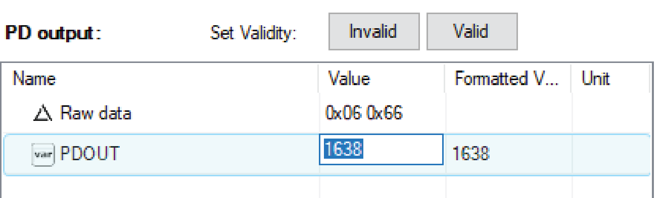
The 12-bit DAC has a 12.5V reference. So, one LSB = 12.5𝑉/4095 = 3.0525mV
To drive the DAC output to 5V, the code to use is calculated as follows:
Code = 5V / 3.0525mV => Code = 1638
Within the TE-Concept GUI, enter this code under the ‘Value’ column for ‘PDOut’ (bottom right of window). The Hex value is shown just above it after entering the code.
To read this PDOut value sent over the IO-Link communication, use the following command.
iold_pde_api_getpdout(pdO_data);
This line of code extracts the PDOUT data from the IO-Link communication and can be used within the program.
This code has a counter that is constantly counting up during the running of the code. The value of this counter can be viewed in the PD input window (Figure 32).
Figure 32. Location to Set Code for DAC Output Voltage.
To send data back (PDIn) to the TE Concept GUI, use the following three lines of code.
pdI_data[1] = (count & 0xff);
pdI_data[0] = ((count >> 8) & 0xff);
iold_pde_api_setpdin(pdI_data, E_VALIDITY_VALID);
Figure 33 shows the lines of code within application.c used in this example. Comments in green explain what is happening in the code.
Figure 33. Code Used for DAC Output Controlled by PDOut.
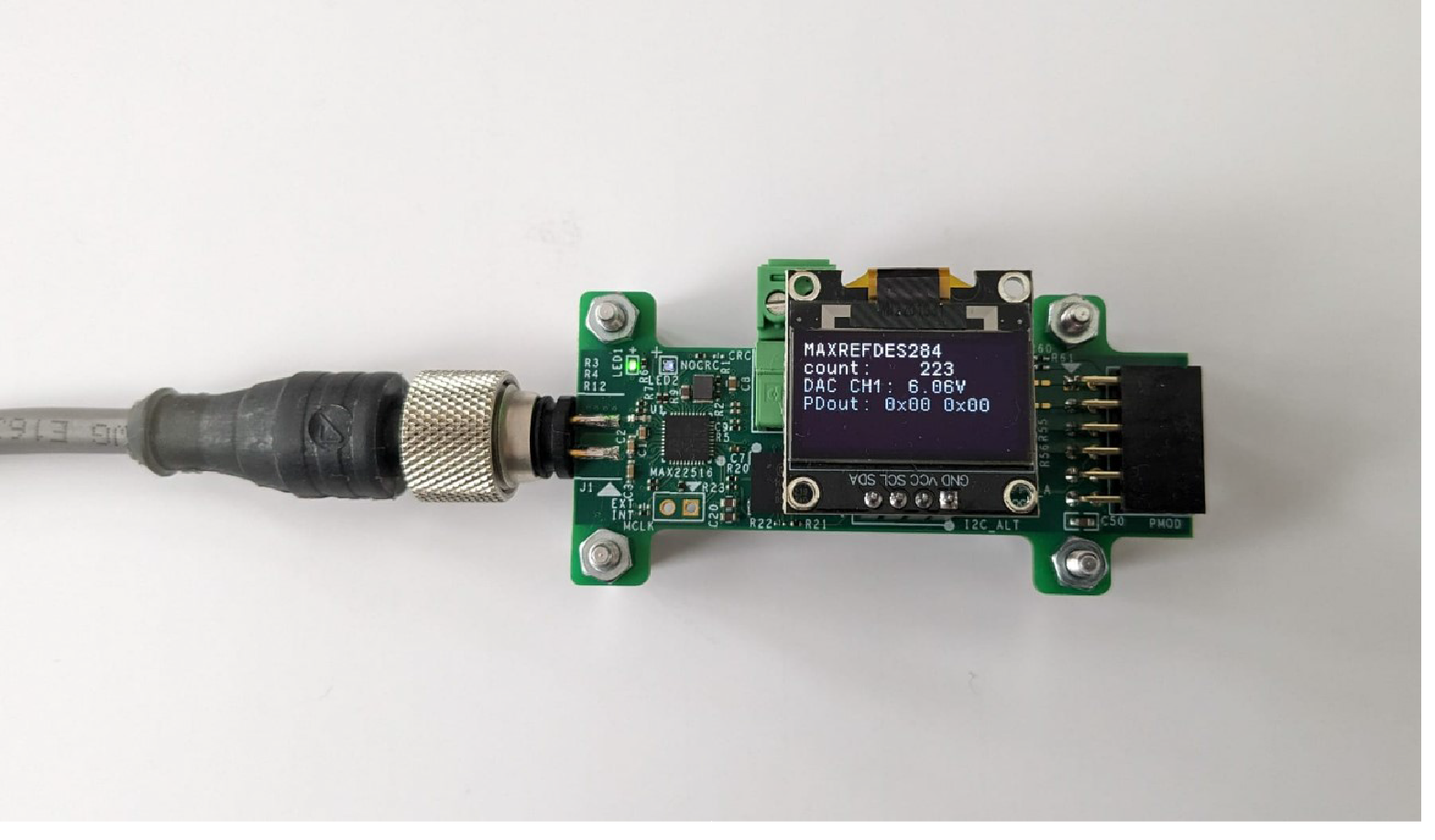
The output voltage can be verified by either measuring the output voltage or by observing the OLED screen. The Hex value is also visible on the last line of the OLED (Figure 34).
Figure 34. OLED Display for DAC Output.
DAC Output Ramping from 0V to Full Scale Depending on Counter Value
For this use case, a counter variable is constantly incrementing and, using bit masking and bit shifting, the DAC output voltage is set based on the counter value. Figure 35 shows the lines of code within application.c used in this example. Comments in green explain what is happening in the code.
Figure 35. Code Used for DAC Output Controlled by Counter.
The actual output voltage of the DAC can be observed by either measuring the output voltage on this channel or by observing the OLED screen.
DAC Output Continuously Ramping
The code in this example continuously ramps the DAC output from low (0.2V) to high (12.31V) and back to low again. When ramping up, the green LED is flashing. It then pauses at the top and ramps down with the red LED flashing. It pauses at the bottom before repeating the sequence. See Figure 36.
Figure 36. Code Used for DAC Output Controlled by Ramp.
All Design Files
Download All Design Files <<MAXREFDES284 Design Files.zip>>
Hardware Files
Schematic
Bill of Materials (BOM)
PCB Layout
Fab Package
IODD-File
Buy Reference Design
Buy Direct: MAXREFDES284#
Trademark List
IO-Link is a registered trademark of Profibus User Organization (PNO).
Windows is a registered trademark and registered service mark of Microsoft Corporation.
Pmod is a trademark of Digilent, Inc.
Search our knowledge base for answers to your technical questions. Our dedicated team of Applications Engineers are also available to answer your technical questions.