The MAXREFDES183 is a complete, portable, battery-powered precision voltage/current calibrator reference design. The MAXREFDES183# supports a fully software-configurable universal IO (analog input or output, voltage or current on a common pin) using the MAX22000 industrial configurable analog IO device. Industry-standard banana plugs are used and include support for Kelvin sensing, remote temperature measurement using a resistance temperature detector (RTD) or a thermocouple, and temperature simulation. The MAXREFDES183# includes built-in temperature compensation and heating capabilities for precision measurements.
The MAXREFDES183#, built in an industrial form factor, features a USB interface and a display with touch control. The system is powered by rechargeable Li-ion (Li+) batteries (user-supplied) with 36-hour (typical) battery life. The Li+ batteries are monitored using a MAX17320 fuel gauge with protector, and can be recharged through USB by the onboard MAX17498A boost converter. All the voltage rails including the higher voltage HVDD and HVSS rails are generated using Analog Devies DC-DC converters from the battery voltage. The complete reference design fits on a 104mm x 83mm printed circuit board (PCB).
The configurable modes include analog voltage input (±10.5V), analog current input (±21mA), analog voltage output (±10.5V), and analog current output (±21mA) across the UIO and GND terminals. The accuracy is as good as 0.01% over a 0 to +50°C operating temperature range.
The MAXREFDES183# is provided as an open PCB but Analog Devices has designed a case for the MAXREFDES183# which can be made with a 3D printer. The design files are included below.
Design files, and software are available on the Design Resources tab. The board is also available for purchase.
Features & Benefits
Portable, Lightweight Precision Calibrator
Accuracy to 0.01% Over a 0 to +50°C Operating Temperature Range
Calibration is the process of comparing an unknown level versus a reference standard of a known value. Or put another way, ‘comparing the measurement of a more accurate instrument with those of a less accurate instrument.’ For example, an output or an input module in programmable logic controllers (PLCs) is required to generate or measure an accurate voltage, current, or temperature. As part of system testing during manufacturing, the module vendor will include a calibration step to make allowances for tolerances in component specifications. Typically, the calibration data are saved onboard, so the module remains calibrated at each power-on. However, over time, electronic equipment may drift due to age, heat, component deterioration, etc., which requires in-the-field calibration updates. In such a case, the technician requires a precision, portable calibrator. The MAXREFDES183# reference design demonstrates a battery-powered calibrator, developed around the MAX22000 industrial universal analog IO device, which is fully software configurable for all common industrial analog input and output, voltage and current ranges.
A device that calibrates other pieces of electronic equipment is commonly called a ‘calibrator.’ There is no universal standard for calibration but typically it includes user-selectable features allowing the ‘calibrator’ to connect to a device under test (DUT) and either provide an accurate source or an accurate measurement to perform system calibration on the DUT. Calibration is important for virtually all analog IO modules or lab equipment or test and measurement products. Calibration and traceability are complex subjects requiring certifications and accreditations. At the simplest level, it is the application of the calibration of process instruments that the MAXREFDES183# is targeted to. The MAXREFDES183# is not intended to be a primary standard level calibrator.
Calibration is vitally important for all electronic equipment, from bench level test and measurement equipment to process automation sensors and modules, all requiring accurate calibration to ensure reliable and safe interoperability. Some items such as specialized automatic test equipment (ATE) used for high-volume daily manufacturing might be calibrated monthly, while other bench equipment such as precision DMMs might be calibrated annually. Even the most expensive equipment requires regular calibration and ensuring the piece of equipment sufficient accuracy to meet its published specifications is necessary to build faith in accepting the performance of the DUT.
A universal analog IO calibrator such as shown with MAXREFDES183#, provides full software configurability for all common analog IOs and temperature sensors, without requiring a field engineer to carry multiple, cumbersome pieces of equipment.
Analog Devices, as a leading provider of configurable IO ICs, also provides complete reference design solutions to help its customers improve their time to market. These proven designs cover all the hardware and software requirements needed for compliance with the analog and digital IO interfaces. The complete reference design fits on a 104mm x 83mm printed circuit board (PCB).
The MAXREFDES183# has four terminals as shown above. The UIO terminal (for voltage/current, input/output), two sense terminals (SNS+ and SNS-), and the ground terminal. The configurable modes include analog voltage input ±10V (+25% over range), analog current input ±20mA (+25% over range), analog voltage output ±10V (+25% over range), and analog current output ±20mA (+25% over range) across the UIO and GND terminals. The MAXREFES183# sets the linear range at 105% and the full-scale range at 125% of the nominal range. The accuracy is as good as 0.01% for voltage mode and 0.02% for current mode over a 0 to +50°C operating temperature range. The other two ‘sense’ terminals can be configured to measure temperature using a standard device such as a PT100 or PT1000 RTD. These terminals interface to the integrated programmable gain amplifier (PGA) in the MAX22000 at inputs AI5 and AI6.
The MAXREFDES183#, built in an industrial form factor, features a USB interface and a display with touch control. The system can be powered using a USB adapter or, for portability, is powered by two rechargeable Li+ batteries (user-supplied) with 36-hour (typical) battery life. The Li+ batteries are monitored using a MAX17320 battery fuel gauge featuring ModelGauge™ m5 functionality. The battery pack can be recharged through USB, the onboard MAX17498A is used as the CV/CC (Constant Voltage/Constant Current) charging circuit The MAX17498A is a flyback converter that boosts the battery pack voltage. All the voltage rails including the higher voltage HVDD and HVSS rails are generated using Analog Devices high-efficiency buck converters. A MAX15462 generates HVDD which is nominally a +20V supply and another MAX15462 generates a -20V HVSS rail. Other buck converters generate the lower voltage rails for 5V, 3.3V, 1.8V, and 1.2V.
The MAXREFDES183# battery-powered precision calibrator design consumes minimal power and space, making it a portable solution for many field calibration tasks for modules and sensors found in various industrial control and automation applications.
The primary IC used in MAXREFDES183# is the MAX22000, an industrial-grade configurable analog IO device configurable on-the-fly in software as a voltage/current input or output. Additional inputs are available to measure other analog signals. The device offers an 18-bit DAC with a fast settling time as well as a 24-bit delta-sigma ADC. This design uses the internal voltage reference. The MAX22000 can meet an accuracy of 0.1% FSR over a ±50°C temperature variation because of the very stable 5ppm/°C internal reference. The MAX22000 sets the linear range at 105% and the full-scale range at 125% of the nominal range, providing a linear range of ±10.5V and a full-scale range of ±12.5V for a nominal range of ±10V. The MAX22000 supports the ADC with a low-noise PGA with high-voltage and low-voltage input ranges to support RTD and TC measurements.
The MAX22000 communicates through a high-speed SPI bus for all configuration and management information as well as conversion results. The MAX22000 operates from 2.7V to 3.6V analog and digital supplies, and up to ±24V high-voltage supplies. The device is available in a 64-pin LGA package and operates over the -40°C to +125°C industrial temperature range.
The MAX31875 is a low-power I2C temperature sensor. The MAXREFDES183# uses two of these temperature sensors, one is placed close to the MAX22000, and the other is placed close to the measurement/source terminals, allowing the MCU to compensate for any temperature differences. The device is available in an ultra-thin WLP/4 package and operates over the -40°C to +145°C industrial temperature range.
The MAX32625 is an ultra-low-power Arm® Cortex®-M4 microcontroller (MCU) with 512KB FLASH and 160KB SRAM. The MAX32625 features a wide range of interfaces including SPI, I2C, and GPIOs. In the MAXREFDES183#, the MCU uses an SPI interface to the MAX22000 and an I2C for the MAX31875 temperature sensors. In addition, the onboard UART connects through an USB-to-UART bridge IC, and an RX/TX pair for the touchscreen display. The device is available in a 68-lead TQFN package and operates over the -30°C to +85°C temperature range.
The MAXREFDES183# features a Nextion NX4024K032 3.2". color display with 400 x 240 pixels. Refer to the MAX22000, MAX31875, MAX32625, and other datasheets for detailed information on the devices.
Thermal Management
Like other precision equipment, the MAXREFDES183# incorporates multiple design techniques to manage thermal performance and improve overall accuracy and stability (Figure 1).
One of the primary sources for the MAX22000 error budget for accurate currents (output or measurement) is the 50Ω resistor, R18. A high-accuracy (0.1%), very stable (0.2ppm/°C) component is specified for MAXREFDES183#.
As mentioned previously, this system uses two onboard temperature sensors (MAX31875) which have an accuracy of ±1°C from 0°C to +70°C, allowing the MCU to accurately determine any temperature gradient between the measurement/source terminals (which connect to the DUT) and the MAX22000, which performs the measurement/source application.
To allow the MAX22000 to be set to a specific ambient temperature, the MAXREFDFES183# incorporates four 'heating resistors' RH1–RH4, which are located close to U1 (MAX22000). These four resistors are 249Ω, 0.25W, and are driven by FETs Q31 and Q32 which are gated by MCU IO pins.
In addition, a small 'metal box', approximately 1in. square, is positioned to cover the MAX22000, the heating resistors, and the local temperature sensor, helping to manage thermal stability for the MAXREFDES183#. The 'metal box' is an RF shield cover, part no. SMS-254 by Leader Tech Inc., but is not intended to specifically manage RF emissions or immunity.
Figure 1. MAXREFDES183# layout for MAX22000.
Battery Pack and Power Supplies
The MAXREFDES183# is designed to accept two Li+ batteries, for example, part no. INR18650-35E, which is a 3.6V, 3500mAh-capacity battery. The MAXREFDES183# is shipped without batteries. The user needs to purchase and install these before using the MAXREFDES183#.
The MAX17320 is a fuel gauge IC with a protector, battery internal self-discharge detection, and optional SHA-256 authentication. The IC monitors the voltage, current, temperature, and state of the battery to protect over/undervoltage, overcurrent, short circuit, over/under temperature, overcharge, and internal self-discharge conditions using external high-side N-FETs. It provides charging prescription to ensure that the battery operates under safe conditions, thereby prolonging the life of the battery. The IC balances the cells using internal FETs. During prequal charging, the IC uses the CHG FET to linearly control charging. The fuel gauge uses Analog Devices' ModelGauge m5 algorithm that combines the short-term accuracy and linearity of a coulomb counter with the long-term stability of a voltage-based fuel gauge to provide industry-leading fuel gauge accuracy. The IC automatically compensates for cell aging, temperature, and discharge rate, and provides accurate state-of-charge (SOC) in milliampere-hours (mAh) or percentage (%) over a wide range of operating conditions.
Thermistor RT1 is located close to the battery pack and monitors the battery temperature. A 0.005Ω current-sense resistor, R51, is included to monitor battery current and a 3A fuse (F5) is included for extra protection. The MAX17320 communicates with the MAX32625 MCU using the I2C bus.
The MAX17498 is a flyback/boost converter with current limiting, which takes the USB-Voltage and boosts it to charge the battery pack. It also feeds the multiple DC-DC buck converters that generate the other voltage rails.
Power solutions use Analog Devices ICs and modules to generate the various voltage rails (System Diagram). A MAX15462 42V, 300mA step-down DC-DC converter generates the HVDD which is nominally a +20V supply, and another MAX15462 generates the -20V HVSS rail. A MAX15062 60V, 300mA step-down DC-DC converter generates the 5V rail, and a MAX17550 60V, 25mA step-down DC-DC converter generates the 3.3V rail. A MAX8840 low-dropout (LDO) regulator follows the 3.3V rail to generate the lower voltage 1.8V rail. Finally, a MAXM17552 compact step-down power module is used to generate the 1.2V rail.
The MAXREFDES183# consumes 110mA (typ) under normal conditions (80% display brightness) and has a typical operation of 31 hours between battery charging cycles. Using standard settings, the display dims down to 10% after 1 minute, extending the battery life to approximately 43 hours.
Detailed Description of Software
The MAXREFDES183# comes with firmware loaded to the MAX32625 MCU. If updates are released, they can be downloaded from the Description & Features section.
Automatic Calibration
The MAXREFDES183# firmware includes processes for automated calibration, and for storing the calibration data on-board. Full details of how to use this procedure are included in the MAXREFDES183# Quick Start Guide.
Precision Calibrator Operating Specification
The MAXREFDES183# was calibrated at room temperature in Analog Devices' lab using the built-in steps described in the Quick Start Guide, and data was taken to show the accuracy and stability in different operating modes over different ambient temperatures as shown in Figures 2 to 6.
Equipment Used:
HP 3458A 8.5 Digit DMM
Keithley 2400 Source Meter
Test Equity 107 Temperature Chamber
Fluke 724 Temperature Calibrator
Figure 2. MAXREFDES183# analog input voltage over temperature.
Figure 3. MAXREFDES183# Analog Input Current Over Temperature
Figure 4. MAXREFDES183# analog output voltage over temperature.
Figure 5. MAXREFDES183# analog output current over temperature.
The MAXREFDES183 will typically be used in an environment with a fixed temperature, for example room temperature in a laboratory, and as such the accuracy at the temperature over time is important to understand, and probably a more useful specification than accuracy over a wide temperature range since it more accurately reflects a real use case. Figure 6 shows the accuracy (defined as drift) of the MAXREFDES183 when operating in Analog Output Voltage Mode. The output was set to 5V, and the output voltage was monitored every 15 minutes over a 7-day (168 hours) period using a National Instruments PXIe 1073 DMM (7.5 digits) demonstrating the excellent stability of the MAX22000 and the MAXREFDES183. The data shows the ppm of reading level drift at room temperature.
Figure 6. MAXREFDES183# analog output voltage stability over time.
Table 1. MAXREFDES183# Specifications
Range
-10V to +10V
Resolution
100µV
Accuracy
±0.01% FSR at room temperature
Stability
±4 ppm of reading, at room temperature
Precision Calibrator 3D Printed Box
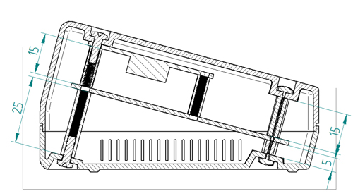
The MAXREFDES183# is provided as an open PCB with metal standoffs as shown in Figure 7. It is optional if the engineer using this board wishes to fit the PCB in a case and there is a 3D printer case design provided by Analog Devices which can be downloaded from the Analog website. Remove the 10mm standoffs supporting the display and replace them with 15mm standoffs. Change the 20mm standoffs for the main PCB and replace them with 5mm and 25mm standoffs as shown in Figure 8 drawing and Figure 9 picture. Note that these extra spacers are not supplied with the MAXREFDES183# and should be sourced by the engineer.
Figure 7. MAXREFDES183# PCB stand-offs.
Figure 8. MAXREFDES183# 3D printed case drawing.
After replacing the standoffs, the board should be as shown in Figure 9.
Figure 9. MAXREFDES183# with updated standoffs.
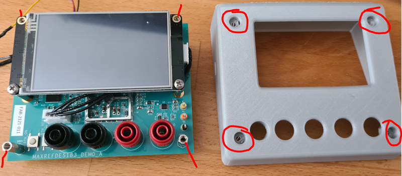
If the engineer has access to a 3D printer and uses the design file provided by Analog Devices, the PCB with the modified spacers can be assembled into the case. Figure 10 shows the mounting details.
Figure 10. MAXREFDES183# 3D case assembly guideline.
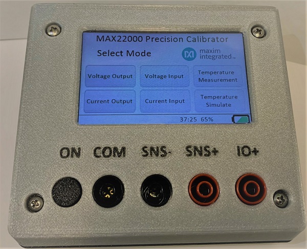
Assuming the 3D printing is completed, the finished assembled unit should be like Figure 11. Note the "ON" button on the left is part of the 3D printed design file.
Figure 11. MAXREFDES183# case.
Restrictions and Warnings for Analog Devices Reference Design Use
The MAXREFDES183# is designed and tested to meet industrial environments. This board and associated software are designed to be used to evaluate the performance of the MAX22000 but are not intended to be deployed as-is into an end product.
The MAXREFDES183# is not for use in functional safety or safety-critical systems.
Search our knowledge base for answers to your technical questions. Our dedicated team of Applications Engineers are also available to answer your technical questions.