The MAXREFDES164# is a complete, high-accuracy, IO-Link®, local temperature sensor reference design that provides excellent temperature accuracy from -20°C to +105°C. Built in an industrial form factor, the design makes use of Maxim’s highly integrated MAX31875 digital temperature sensor with an I2C interface.
The MAX31875 operates over the -50°C to +150°C temperature range and measures temperatures from -40°C to +145°C with ±1.5°C accuracy. The temperature sensor performs more accurate temperature conversions from 0°C to +70°C (±1.0°C).
A MAX32660 microcontroller interfaces between the MAX31875 temperature sensor and the MAX14828 IO-Link® device transceiver. All three Maxim products are in wafer-level packages (WLPs), allowing the MAXREFDES164# to have a tiny footprint—under an inch in length. The 3.3V and 5V rails are generated by utilizing the two integrated LDO regulators within the MAX14828, which saves external components and space. In addition, the three Maxim ICs are low-power devices, allowing this reference design to consume minimal power with low thermal dissipation.
This sensor utilizes either the TMG TE IO-Link device stack or the TEConcept IO-Link device stack to communicate with any IO-Link version 1.1-compliant master. The board contains a male M12 connector for connection to a compliant IO-Link master using a standard M12 cable. Connecting the MAXREFDES164# to a USB IO-link master, such as the MAXREFDES165#, with the associated software allows for easy evaluation with a PC.
Note: The default stack that ships with the MAXREFDES164# is the TMG version. Contact the factory if you require the TEConcept version.
Design files, firmware, and software can be found on the Design Resources tab. The board is also available for purchase.
Features & Benefits
IEC 61131-9
TMG TE IO-Link Stack or TEConcept IO-Link Stack
IO-Link version 1.1 compliant
Measures Temperature from -40°C to +105°C with ±1.5°C Accuracy
Advanced factory automation solutions, such as Industry 4.0, require increasing numbers of smart sensors, which are typically controlled using IO-Link for the point-to-point serial communication between the sensor and controller (master). As a leading provider of IO-Link sensor transceiver and master transceiver ICs, Maxim also provides complete reference design solutions to help our customers improve their time to market. These proven designs cover all the hardware and software requirements needed for compliance with the IO-Link standard. The complete MAXREFDES164# reference design, including all of the ICs and external protection devices such as varistors, is provided on a 25.4mm x 7.5mm printed circuit board (PCB).
Maxim Integrated collaborated with Technologie Management Gruppe Technologie und Engineering (TMG TE) and TEConcept in designing the MAXREFDES164# as a temperature sensor reference design that is compliant with the IO-Link version 1.1/1.0 standard. The MAXREFDES164# design consists of an industry-standard MAX14828 IO-Link device transceiver, a MAX32660 ultra-low-power 16-bit microcontroller utilizing either the TMG TE IO-Link device stack or the TEConcept IO-Link device stack, and a MAX31875 local temperature sensor. Figure 1 shows the system block diagram.
The MAXREFDES164# IO-Link local temperature sensor consumes minimal power, space, and cost, making it a complete solution for many industrial control and automation local temperature-sensing applications.
The MAX14828 IO-Link device transceiver is compliant with the IO-Link version 1.1/1.0 physical layer specification. It integrates the high-voltage functions commonly found in industrial sensors, including drivers and regulators, all in a tiny 2.5mm x 2.5mm WLP. The MAX14828 features two ultra-low power drivers with active reverse-polarity protection. Operation is specified for normal 24V supply voltages up to 60V. Transient protection is simplified due to high voltage tolerance (65V absolute maximum rating), allowing the use of varistors or micro TVS diodes.
The device features a flexible control interface. An SPI interface is available with extensive diagnostics, and a 3-wire UART interface is provided for IO-Link operation. The MAXREFDES164# takes advantage of the multiplexed UART/SPI option, which allows using one serial microcontroller interface for shared SPI and UART interfaces. The MAX14828 includes integrated 3.3V and 5V linear regulators, which provide the low-noise supply rails for the other components on the board.
The MAX32660 is an ultra-low power, cost-effective, highly integrated microcontroller that combines a flexible and versatile power-management unit with the powerful Arm® Cortex®-M4 with floating point unit (FPU). The device integrates up to 256KB of flash memory and 96KB of RAM to accommodate application and sensor code. It supports SPI, UART, and I2C communication in a tiny form factor—1.6mm x 1.6mm 16 WLP.
The MAX31875 is a ±1°C-accurate local temperature sensor with an I2C/SMBus interface. The combination of a tiny package and excellent temperature measurement accuracy makes this product ideal for a variety of equipment. The MAX31875 measures temperature and converts the data into digital form, then the I2C-compatible, 2-wire serial interface allows access to conversion results. Standard I2C commands allow reading the data and configuring other operating characteristics. The MAX31875 is available in a 4-bump WLP and operates over the -40°C to +145°C temperature range.
For protection, the MAXREFDES164# uses varistors (MOV) at the IO-Link interface. The VC060330A650DP varistors have a working voltage of 30V and a breakdown voltage of 41V. Due to these varistors, this reference design meets both IEC 61000-4-2 (ESD) and IEC 61000-4-4 (EFT). It is designed to meet surge capability (2A at t = 1.2/50μs) and to have a low clamping voltage of <70V. The MAX14828 absolute maximum (abs max) voltage rating of 65V on the IO-Link pins allows the use of these tiny, simple varistors where other vendors transceiver ICs with lower abs max ratings require much larger sized TVS diodes.
The MAXREFDES164# uses an industry-standard M12 connector allowing a 4-wire or a conventional 3-wire cable to be used, which keeps costs low. The MAXREFDES164# consumes less than 6mA (typ), including the green LED “alive signal” which pulses rather than remaining constantly on to reduce power consumption. Note that the red LED indicates a FAULT condition if illuminated.
Detailed Description of Software
As seen in Figure 2, the MAXREFDES164# was verified using the TMG TE IO-Link Device Tool V5, which comes with the MAXREFDES165# IO-Link master. Download the IODD file (*.xml) located in the Design Resources tab and go to the Quick Start Guide section below for step-by-step instructions on how to use the software. Figure 3 shows a screenshot of the TMG TE IO-Link Device Tool V5 communicating with the master and sensor.
Note: In this and the following sections, the MAXREFDES164# is demonstrated with the MAXREFDES165# 4-port IO-Link master and the TMG IO-Link Device Tool. The MAXREFDES164# also works seamlessly with the MAXREFDES145# 8-port IO-Link master and the TEConcept IO-Link Control Tool.
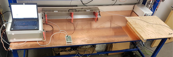
Figure 2. The MAXREFDES164# reference design (right) connected to MAXREFDES165# IO-Link master reference design (left) for verification.
Figure 3. The TMG TE IO-Link Device Tool with the MAXREFDES164#.
Detailed Description of Firmware
The MAXREFDES164# ships preprogrammed as a working IO-Link temperature sensor ready to connect to an IO-Link master. The firmware targets a MAX32660 microcontroller and follows the simple flow chart shown in Figure 4. The firmware utilizes the TMG TE IO-Link device stack. After hot plug-in, the MAXREFDES164# waits for a wake-up signal from the IO-Link master. After receiving the wake-up signal, the MAXREFDES164# synchronizes to the IO-Link master's 230.4kbps baud rate (COM3). Communication parameters are exchanged. The MAXREFDES165# then starts a cyclic data exchange by requesting the sensor process data. If the sensor is removed, the IO-Link master will detect a missing sensor.
Figure 4. The MAXREFDES164# firmware flow chart.
The TMG TE IO-Link Device Tool Windows®-compatible software features IODD file import capability, connects to a PC through USB, and is available to download from the Design Resources tab of the MAXREFDES165#. The TMG IO-Link Device Tool software is shown in Figure 3, and a complete step-by-step Quick Start Guide is also downloadable from the Design Resources tab of the MAXREFDES165#.
Source code for the MAXREFDES164# is not provided. The TMG TE IO-Link device stack ships preprogrammed in the MAXREFDES164# hardware with a perpetual license. TMG TE contact information is as follows:
TMG Technologie Management Gruppe
Technologie und Engineering GmbH
Zur Gießerei 10
76227 Karlsruhe
Phone: +49 721 828 060
Fax: +49 721 828 0610
Note: The MAXREFDES164# is also supported by TEConcept firmware, demonstrating the complete interoperability of Maxim products such as the MAX14828. The default stack that ships with the MAXREFDES164# is the TMG version. Contact the factory if you require the TEConcept version.
The TEConcept IO-Link stack ships preprogrammed in the MAXREFDES164# hardware with an infinite time license.
List of trademarks ›
Arm is a registered trademark and service mark of Arm Limited.
Cortex is a registered trademark of Arm Limited.
Haefely is a registered trademark of Haefely Test AG.
FTDI is a registered trademark and service mark of Future Technology Devices International Limited.
IO-Link is a registered trademark of Profibus User Organization (PNO).
Teseq is a registered trademark of Ametek CTS.
Windows is a registered trademark and registered service mark of Microsoft Corporation.
To test the sensor accuracy, the MAXREFDES164# was placed in a temperature chamber and the measured temperature was compared to the chamber temperature, as measured with a precision instrument. Figure 5 shows the accuracy vs. temperature over the -40°C to +125°C range. Note the higher temperature is limited by the MAX32660 microcontroller operating range of +105°C, but for this case we tested to +125°C. The accuracy over the entire temperature range is well within the target specification of ±1.5°C from the MAX31875 data sheet.
Figure 5. Accuracy vs. temperature for the MAXREFDES164#.
EMC Testing
The MAXREFDES164# was tested in Maxim’s lab for the common industrial compliance standards, and the test methodology and results are presented in this section.
Equipment Used
MAXREFDES164# IO-Link Sensor and MAXREFDES145# IO-Link Master
Haefely® Technology ECompact4 EFT/Surge Generator
Teseq® CDN 117 Signal Line Coupling Network
Teseq CDN 3425 EFT Data Line Coupling Clamp
Teseg NSG438 ESD Generator
Surge Testing
The MAXREFDES164# was tested to withstand up to ±1.2kV of 1.2/50µs IEC 61000-4-5 surge with a total source impedance of 500Ω. Surge testing was performed using the MAXREFDES145 IO-Link master, and 10 surge pulses were applied for each test as shown in Table 1. The MAXREFDES164# was not damaged by the tests.
L+ to GND: Communicating with the master, the module continued to execute code and transfer data, and the MAX14828 registers were not corrupted. CQ to GND: Communicating with the master, the module continued to execute code and transfer data, but the MAX32660 needed to be reset for -1.2kV. L+ to CQ: Communicating with the master, the module continued to execute code and transfer data, but the MAX32660 needed to be reset for -1.2kV.
Table 1. Surge Test Results
Test Condition
L+ to GND
CQ to GND
L+ to CQ
+1kV
Pass
Pass
Pass
-1kV
Pass
Pass
Pass
+1.2kV
Pass
Pass
Pass
-1.2kV
Pass
Pass with reset
Pass with reset
Figure 6. Surge testing setup.
Figure 7. Surge testing.
EFT/Burst Testing
Using a 5m IO-Link cable with standard M12 connectors, the MAXREFDES164# was tested to withstand electrical fast transient (EFT)/burst up to ±4kV according to IEC 61000-4-4. EFT testing was performed using the MAXREFDES145 IO-Link master, and 10 EFT pulses were applied for each test, as shown in Table 2. Repetition rates of 5kHz and 100kHz were tested, along with burst lengths of 15ms and 0.75ms. The MAXREFDES164# was not damaged by the test, and the MAX14828 registers were not corrupted.
Table 2. EFT/Burst Test Results
Test Condition
5kHz/15ms
100kHz/0.75ms
+4kV
Pass
Pass
-4kV
Pass
Pass
Figure 8. EFT/burst testing.
ESD Testing
The MAXREFDES164# was tested to withstand electrostatic discharge (ESD) for Contact and Air-Gap discharge up to ±4kV according to IEC 61000-4-2. EFT testing was performed on the MAXREFDES164#, and then operation was tested using the MAXREFDES145 IO-Link master to transfer data, as shown in Table 3. The MAXREFDES164# was not damaged by these tests and continued to operate normally.
To test the MAXREFDES164# sensor, connect it to a port of an IO-Link master. In the following example, a MAXREFDES165# master is used, but any IO-Link compliant master and associated IO-Link device GUI should work.
Required Equipment
Supplied by Maxim:
MAXREFDES164#
Note: Download files from the Design Resources tab.
user Supplied:
IO-Link master (for example, the MAXREFDES165#) with an AC-to-DC 24V power adapter
TMG IO-Link Device Tool Software
One IO-Link Cable
USB 2.0 Type B Cable (for Use with the MAXREFDES165#)
Windows 7, Windows 8, or Windows 10 PC with a USB Port
Note: For details of steps 1–5, see the Design Resources tab of the MAXREFDES165#.
Install the IO-Link master software tool. See the MAXREFDES165# Quick Start Guide in the Design Resources tab of the MAXREFDES165# for installing the TMG TE IO-Link Device Tool V5 software.
Install the FTDI® driver. See the Design Resources tab of the MAXREFDES165# for details.
Connect the USB cable from the PC to the MAXREFDES165# board.
Connect the AC-to-DC 24V DC-power converter.
Run the TMG TE IO-Link Device Tool V5 software and connect to the MAXREFDES165# board.
Double-click the display master. The GUI will show that a 4-port IO-Link master is connected. Click Go Online and the four red LEDs on the MAXREFDES165# should turn on.
Sensor Testing Procedure
Connect the female end of the IO-Link cable to the MAXREFDES164#.
Connect the male end of the IO-Link cable to one of the ports on the MAXREFDES165#.
Import the IODD file for the MAXREFDES164#.
The device (the MAXREFDES164#) should be found and listed within the GUI. Select Takeover devices into engineering, as shown in Figure 10.
Figure 10. MAXREFDES164# sensor found.
Double-click on the device to open and display the data from the MAXREFDES164# IODD file, as shown in Figure 11.
Figure 11. MAXREFDES164# IODD.
Select the Process Data tab, as shown in Figure 12.
Figure 12. MAXREFDES164# process data out.
Apply heating or cooling to the sensor to continuously update the data as temperature in °C.
Search our knowledge base for answers to your technical questions. Our dedicated team of Applications Engineers are also available to answer your technical questions.