CN0416


Overview
Design Resources
Design & Integration File
- Schematic
- Bill of Materials
- Gerber Files
- PADS Files
- Assembly Drawing
Evaluation Hardware
Part Numbers with "Z" indicate RoHS Compliance. Boards checked are needed to evaluate this circuit.
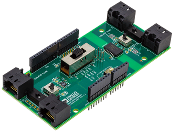
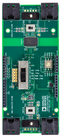
- EVAL-CN0416-ARDZ ($58.85) Isolated/Non-Isolated RS-485 Transceiver
Features & Benefits
- Full and Half Duplex Selection
- Isolated and non-Isolated RS-485
- Up to 16 MBPS transmission
- Multinode connection using onboard rotary encoder
Product Categories
Parts Used
Documentation & Resources
-
CN0416 - User Guide Wiki6/11/2019WIKI
Circuit Function & Benefits
The TIA/EIA-485-A, the most widely used transmission line standard of the telecommunication industry, describes the physical layer of the RS-485 interface and is normally used with a higher level protocol, such as Profibus, Interbus, Modbus, or BACnet. Applications include process control networks, industrial automation, remote terminals, building automation (such as heating, ventilation, air conditioning (HVAC)), security systems, motor control, and motion control. The RS-485 interface allows for robust data transmission over relatively long distances (up to 1 km).
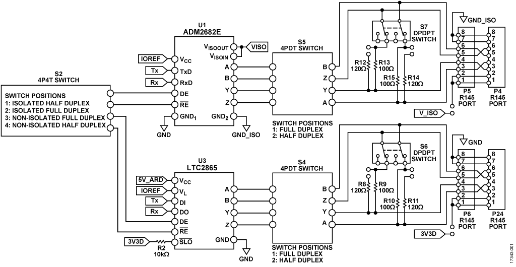
The circuit shown in Figure 1 is a universal RS-485 communication platform, implementing both isolated and nonisolated RS-485 designs. The nonisolated circuit provides an extended common-mode range of ±25 V, improving on the RS-485 specification of −7 V to +12 V and avoiding the need for isolation in many applications, such as the case when all nodes are supplied and referenced to the same power and ground lines.
The isolated interface, however, allows up to 500 V between the controller ground and RS-485 signals for large scale systems requiring robust communications between remote nodes, such as building-to-building communications. Eliminating commonmode effects in long haul networks requires nodes or repeaters to be isolated from one another and the isolated transceiver, certified in accordance with the UL1577, allows protection and insulation for up to 5000 V between the controller ground and RS-485 signals (1 minute, per UL1577).
The circuit is configurable to operate in full-duplex and halfduplex operations, depending on the application. The termination for each connection can be open or resistance terminated, which allows customers to easily add or remove nodes to the bus lines. Furthermore, the termination resistance is configurable to support standard RS-485 cables or CAT5 Ethernet cables. Power to the device can be sourced from an onboard supply or from the bus power lines.
The circuit can be used for point to point systems or multidrop systems using the onboard address selector. Each circuit can be set as a master device or slave device, depending on the particular application and network in which it is used. The onboard 10-pin connector, compatible with the ADALMUARTJTAG, allows the master to act as the gateway between a host computer and the RS-485 bus via a USB virtual COM port.

Circuit Description
RS-485 Bus Standard
The RS-485 bus standard is one of the most commonly used physical layers in industrial applications needing local networks capable of multidrop communication links and long haul data transfer over distances up to 1200 m. A data rate of 10 Mpbs is achievable for cable lengths up to 12 m, dropping to 100 kbps at 1200 m, as shown in Figure 2.

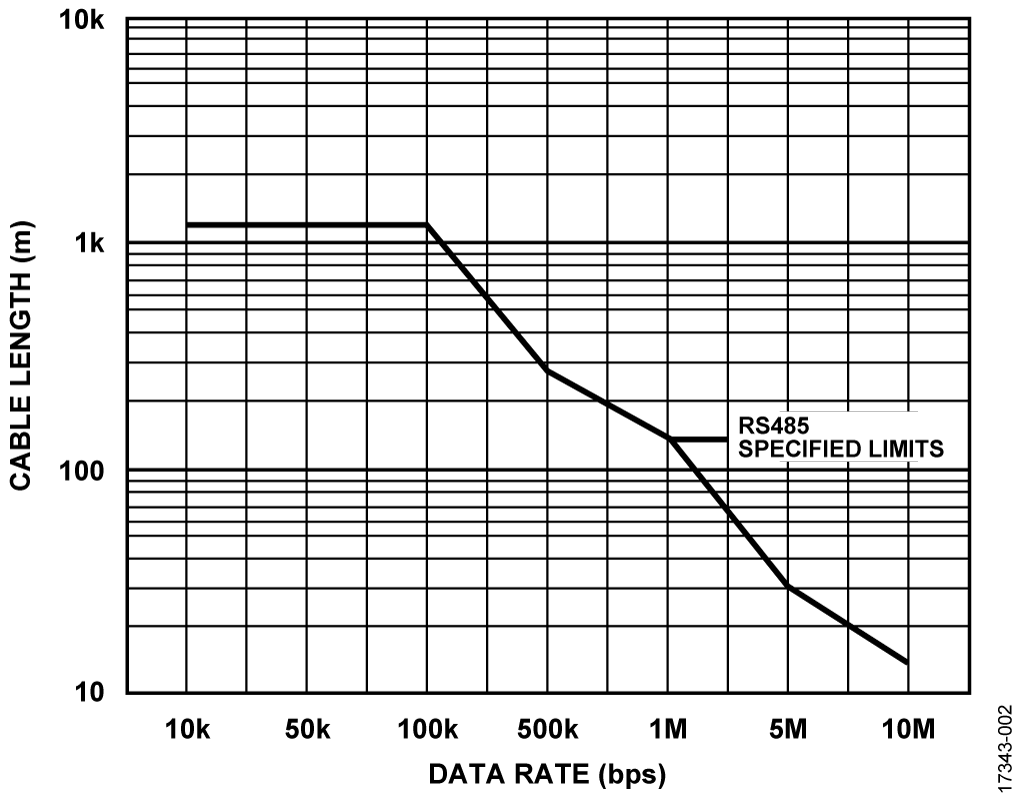
Table 1 shows the some of the specifications of the RS-485 bus standard, as well as the improved specifications that the ADM2682E and LTC2865 provide.
For the full details of each transceiver device, refer to their data sheets. The extended specifications of the ADM2682E and LTC2865 improve the robustness of systems that are nominally compliant but may occasionally experience events that break the standard. For example, two equipment cabinets in a factory may both be tied to earth ground, with a few volts ac between grounds. However, an ESD strike to one cabinet may momentarily drive its common-mode voltage to 20 V. An LTC2865 rides through such an event, while a transceiver that just meets the standard may produce corrupt data or fail entirely.
The ADM2682E greatly extends common-mode tolerance, allowing for 25 kV/μs transient immunity, with up to 5000 V potential difference between devices (1 minute, per UL1577). Refer to the ADM2682E data sheet for details on safety and regulatory approvals.
| Specification | Standard | ADM2682E | LTC2865 |
| Data Rate | 10 Mbps | 16 Mbps | 20 Mbps |
| Driver Output Applied Voltage Range | −7 V to +12 V | −9 V to +14 V, isolated | −60 V to +60 V |
| Receiver Input Voltage Range | −7 V to 12 V | −9 V to +14 V, isolated | −60 V to +60 V |
| Receiver Input Sensitivity | ± 200 mV | −200 to −30 mV | ±200 mV |
| Cable Length | Up to 1200 m | Up to 1200 m | Up to 1200 m |
| Receiver Input Resistance | ≥12 kΩ | 96 kΩ | 112 kΩ |
| Number of Drivers and Receivers | 32 drivers | 256 drivers and receivers | 256 drivers and receivers |
| 32 receivers |
The inclusion of the isolated and nonisolated transceivers on EVAL-CN0416-ARDZ aids in determining the actual requirements and implementation of the end application.
The circuit has four on-board Ethernet jacks, one pair for isolated and one pair for nonisolated communications. Whereas Ethernet cable is not intended for RS-485 applications, and the impedance is 100 Ω vs 120 Ω for RS-485, the ubiquity of common CAT5 and CAT6 cables provides a convenient way to build prototype systems during development. Also, each pair of Ethernet ports have crossover pin configurations, allowing the use of straight-through Ethernet cables for multinode systems. Connection points to the RS-485 signals are provided, facilitating the use of other connectors, or direct wiring to theRS-485 cable of the application.
RS-485 Bus Node Capacity
Both the ADM2682E and LTC2865 have 1/8 unit loading of 96 kΩ minimum, allowing up to 256 nodes in a single bus system. (The RS-485 standard specifies a receiver input impedance of 12 kΩ and a maximum of 32 nodes.)
Termination
A common guideline for termination is to terminate lines transmitting signals with rise/fall times less than four times the propagation delay of the cable. A standard CAT5 cable has a propagation delay of 4.8 ns/m to 5.3 ns/m. The ADM2682E and LTC2865 have maximum rise/fall times of 15 ns. Thus, for lines greater than 0.78 m in length, it is recommended to use termination. For best practice, properly terminate all RS-485 systems.

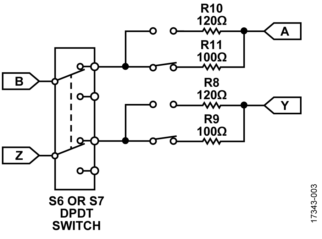
The circuit shown in Figure 3 can configure the RS-485 line termination to either a differential resistance or left open via S7 for isolated communications and via S6 for nonisolated communications. The full-duplex RS-485 standard requires a termination at the master node and the farthest slave node.
For a half-duplex connection, terminate both ends of the transmission cable. The value of the termination resistance should be equal to the characteristic impedance of the cable. For CAT5 cables, this is 100 Ω. By default, the circuit uses a 100 Ω termination resistance but can be configured through solder links to use the standard RS-485 termination resistance, which is 120 Ω. Table 2 shows the advantages and disadvantages of open and terminated RS-485 communications.
| Termination | Advantages | Disadvantages |
| Open or No | Simple, low power | For slow and short |
| Termination | Communications | |
| Parallel | Supports long | High power |
| Resistance | Distance and Fast | |
| Communications |
Half Duplex Operation

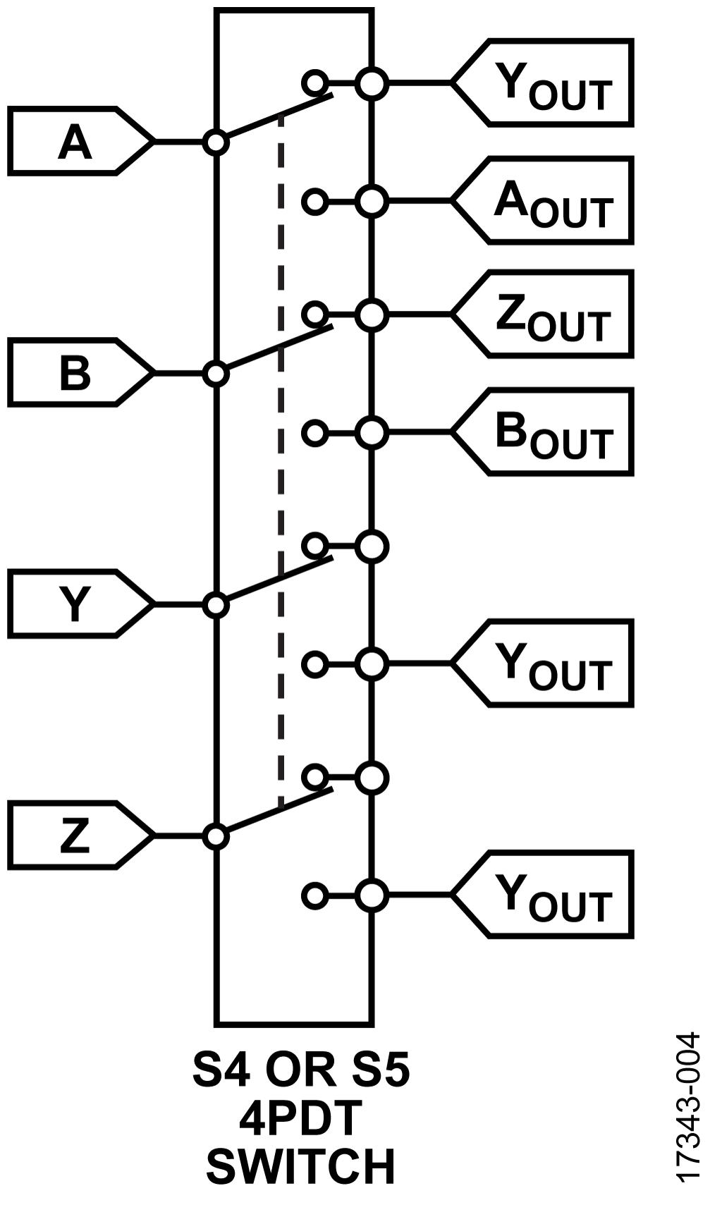
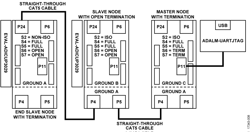
The circuit shown in Figure 4 can be set to operate in halfduplex mode for both isolated and nonisolated communications via Switch S5 and Switch S4, respectively. The driver noninverting output is shorted with the noninverting input of the receiver, whereas the inverting output of the driver is shorted with the inverting input of the receiver. This configuration allows for a 2-wire RS-485 network, but the bus can only accommodate data transmission in one direction at a time. The driver and receiver enable pins are required to assure that only one driver is enabled to send data at a time. Figure 5 shows the connection setup for a three-slave node half-duplex isolated RS-485 communication. Slave nodes are connected through similar Ethernet jacks. For example, Slave A P5 is connected to Slave B P5 using a straight-through CAT5 cable. The master node is connected to a slave node via an opposite Ethernet jack. For example, Slave A P5 is connected to P4 of the master node using a straight-through CAT5 cable.


| Type of Node |
Switch Settings |
| Master Node with Termination | S4 = half duplex, S5 = half duplex |
| S6 = terminated, S7 = terminated | |
| Slave Node with Open Termination | S4 = half duplex, S5 = half duplex |
| S6 = open, S7 = open | |
| End Slave Node with Termination | S4 = half duplex, S5 = half duplex |
| S6 = terminated, S7 = terminated |
Full-Duplex Operation
The circuit shown in Figure 5 can be set to full-duplex mode for both isolated and non-isolated communications via S5 and S4, respectively. In full-duplex mode, the circuit uses all receiver and driver inputs and outputs, respectively. This allows for a 4-wire RS-485 network and can accommodate simultaneous data transmission in both directions between master and slave nodes. Figure 6 shows the connection setup for a three-slave node full-duplex non-isolated RS-485 communications. Slave nodes are connected through similar Ethernet jacks when using straight-through Ethernet cables. For example, Slave A P6 is connected to Slave B P24 using a straight-through CAT5 cable. The master node is connected to a slave node via an opposite Ethernet jack. For example, Slave A P6 is connected to P24 of the master node using a straight-through CAT5 cable.

| Type of Node | Switch Settings |
| Master Node with Termination | S4 = full duplex, S5 = full duplex |
| S6 = terminated, S7 = terminated | |
| Slave Node with Open Termination | S4 = full duplex, S5 = full duplex |
| S6 = open, S7 = open | |
| End Slave Node with Termination | S4 = full duplex, S5 = full duplex |
| S6 = terminated, S7 = terminated |
True Fail-Safe Receiver Inputs
In multinode systems, a bus idle condition occurs when all nodes are in receive mode. In the bus idle condition, the differential input voltage is 0 V. Previous generation RS-485 receivers required external fail-safe termination and biasing to prevent the bus idle condition from producing erroneous data. Both ADM2682E and LTC2865 tolerate bus idle conditions without external circuitry.
The ADM2682E has true fail-safe receiver inputs with a differential input threshold voltage to −200 mV to −30 mV. Thus, the 0 V differential input voltage is received as a defined logic level and prevents random erroneous data from entering or impacting the system.
When a device requires an adjustment to the input threshold voltage, the adjustment causes duty cycle asymmetry at the receiver output, which worsens at low input signal levels and slow input edge rates. The LTC2865 has a full fail-safe operation without adjusting the input threshold voltage. Instead of adjusting the input threshold voltage, the LTC2865 uses an internal window comparator to determine if the input voltage falls between the positive and negative thresholds. If this failsafe condition persists for more than 3 μs, the fail-safe condition asserts and the signal is forced to a high state.
Signal and Power Isolation
The CN-0416 circuit can be configured via Switch S2 to use either isolated communications through the ADM2682E or non-isolated communications through the LTC2865.
When using a straight-through Ethernet cable to connect an isolated Ethernet jack to a non-isolated Ethernet jack between two slave nodes, connect P4 to P24 and connect P5 to P6. In contrast, when connecting between a master and a slave node in the same situation, connect P4 to P6 and connect P5 to P24. When the same electrical system is used to power the supplies of all nodes, connecting them all to the same earth ground may reduce the noise produced by ground currents flowing between nodes at different ground potentials. For the single earth ground configuration, the non-isolated RS-485 communication is most applicable.
When different nodes are powered by different electrical systems, especially when they are situated in different buildings, may increase the impedance of the earth ground, which in turn, increases the likelihood of ground currents between nodes. For potential ground current situations, isolated RS-485 communication is required. The ADM2682E has 5 kV rms signal isolation using an Analog Devices, Inc., iCoupler® data channel. The ADM2682E also has 5 kV rms power isolation implemented using an Analog Devices isoPower®, integrated, isolated dc-to-dc converter.
Common Variations
The RS-485 lines present in the Ethernet port are the driver and receiver inverting and noninverting inputs, as well as supply and ground lines. Alternative designs use a regular screw terminal for easy wiring of standard RS-485 cables and also include a connection for the shield.
The EVAL-CN0416-ARDZ board has a connector compatible with the ADALM-UARTJTAG programming board to easily interface with a PC. Furthermore, the USB-to-serial converter can be selected to have a 3.3 V supply output, achieving current requirements of the ADM2682E and LTC2865 that eliminate the need for the ADP7102 low dropout regulator. The on-board hex switch can also be removed to reduce cost and the number of general-purpose inputs/outputs (GPIOs), using instead, a full software implementation for node addressing.
Circuit Evaluation & Test
The EVAL-CN0416-ARDZ board has a connector compatible with the ADALM-UARTJTAG programming board to easily interface with a PC. Furthermore, the USB-to-serial converter can be selected to have a 3.3 V supply output, achieving current requirements of the ADM2682E and LTC2865 that eliminate the need for the ADP7102 low dropout regulator. The on-board hex switch can also be removed to reduce cost and the number of general-purpose inputs/outputs (GPIOs), using instead, a full software implementation for node addressing.
Both setups use the EVAL-CN0416-ARDZ circuit evaluation board, the ADALM-UARTJTAG programming board, and the EVAL-ADICUP3029. Serial terminal software is required to send and display test messages. It is recommended to use a serial terminal software, such as Tera Term, that automatically reconnects after plugging or unplugging a device.
Equipment Needed
- PC with a USB port and Windows 7 (32-bit) or higher
- EVAL-CN0416-ARDZ circuit evaluation boards
- ADALM-UARTJTAG boards
- Straight-through RJ45 CAT5/CAT5E cables
- USB to micro-USB cables
- EVAL-ADICUP3029 with their corresponding power supply adapter (loaded with the CN-0416 multinode fullduplex example code)
Getting Started
A detailed user guide for the EVAL-CN0416-ARDZ is available on the Analog Devices Wiki. Consult this user guide for all aspects of hardware and software operation.
Before powering all test setups, set the on-board switches in the EVAL-CN0416-ARDZ to the communication settings corresponding to the test setup.
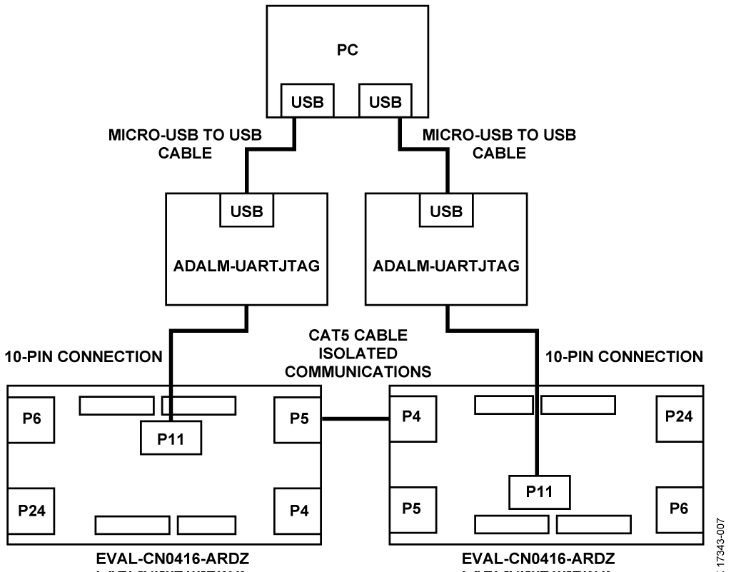
Direct Communications Test Setup and Functional Block Diagram
Set the on-board switches of each EVAL-CN0416-ARDZ board to full duplex with termination. The user can opt to either use isolated or nonisolated communications.
To set up the connection diagram shown in Figure 7, take the following steps:
- Connect the two EVAL-CN0416-ARDZ boards to the two ADALM-UARTJTAG boards via the P11 jumper header.
- Connect the two EVAL-CN0416-ARDZ boards together using a straight-through CAT5 cable.
- For isolated communications, connect P4 of one board to P5 of the other board or vice versa. Figure 7 shows the setup connections for isolated communications
- For nonisolated communications, connect P6 of one board to P24 of the other, or vice versa.
- Connect the two ADALM-UARTJTAG programming boards to the PC using the USB-to-microUSB cables.
- Be sure to identify the correct virtual COM ports used by the two ADALM-UARTJTAG boards.
- On the PC, connect to the first EVAL-CN0416-ARDZ via a serial terminal connection. Ensure that the baud rate and COM port are set properly.
- On the PC, connect to the second EVAL-CN0416-ARDZ via a second serial terminal connection. Ensure the baud rate and COM port are set properly.
- The two serial terminals are now connected to each other via RS-485 communications.
Any message sent by the one terminal is received by the other terminal. Messages between the two serial terminals can be sent and received simultaneously.

Multinode Network Test Setup and Functional Block Diagram
Figure 8 shows a multinode network setup using both isolated and nonisolated RS-485 transceivers with two different slave nodes interfaced by the EVAL-ADICUP3029. Set up the onboard switches of each EVAL-CN0416-ARDZ board as indicated in Figure 8. Set the hexadecimal selection switch of each board to unique address values.
To setup the network shown in Figure 8, take the following steps:
- Connect the P11 10-pin connector of the master node to the ADALM-UARTJTAG.
- Connect the EVAL-CN0416-ARDZ boards in the indicated ports (shown in Figure 8) using straight-through Ethernet cables.
- Connect the ADALM-UARTJTAG to the PC using the USB-to-microUSB cable.
- Identify the correct virtual COM port used by the ADALM-UARTJTAG.
- Open the serial terminal software to connect to the serial port with the baud rate defined by the wiki user guide.
- Select a slave node to communicate by sending its hexadecimal address (0 to 9 and A to F).
- Any lowercase letters sent by the master are encrypted by the slave node using a Caesar cipher and sent back to the master, simultaneously.
Power Supply Configuration
When connected appropriately to the ADALM-UARTJTAG or to the EVAL-ADICUP3029, the EVAL-CN0416-ARDZ evaluation board receives the necessary voltage to power the circuit.