How to Use GMSL Line-Fault Detection for Power Over Coax
Abstract
Many of Maxim GMSL SerDes parts have built-in line-fault detection circuits for a short to ground, short to the battery, and a disconnected cable. When power over coax (PoC) is used, a different configuration is required for proper line-fault operation. This application note explains the line-fault circuitry, how to adapt it for PoC, and a solution to protect against overvoltage and overcurrent conditions.
Introduction
In any application that uses a cable between devices, it is good to be able to diagnose faults in the line without needing to physically inspect the devices. Many of Maxim’s GMSL parts include line-fault circuitry to detect a short to ground, short to the battery, and a disconnected cable. This application note discusses how to adapt GMSL line-fault circuitry for power over coax (PoC) and offers a solution to protect against overvoltage and overcurrent conditions. The MAX96705 and MAX96706 SerDes pair are an example. When both serializer and deserializer have local power sources, the coax cable is biased through external resistors R1, R2, and R5 as shown in Figure 1.

Figure 1. Line-fault detection without PoC.
Power over coax is exactly what it sounds like, the transmission of power over a coax cable. It is also known as phantom power, i.e., when power and data share the same cable. High-speed serial data, UART/I2C commands, and DC power are all present on the coax cable in a GMSL PoC application.
Originally, GMSL parts were designed to detect faults in twisted-pair systems without PoC. If PoC and line-fault detection are both desired, an alternate circuit is required for proper operation. The coax cable is biased at a voltage set by the power supply, typically between 5V and 12V for camera applications. In this case the line-fault resistors must be reconfigured, and PoC filters are required to inject and extract DC power from the high-speed GMSL link. See Figure 2 for the new configuration.

Figure 2. Line-fault detection for PoC.
Line-Fault Internal Circuitry
Inside the chip, the line-fault detector has a multilevel comparator to detect the possible line conditions: short to ground, short to the battery, a disconnected cable, and normal operation. This is shown in Figure 3. Table 1 lists the MAX96706 line-fault detection input comparator electrical specs from its data sheet.

Figure 3. Internal multi-level line-fault comparator.
| Parameter | Symbol | Min | Typ | Max | Units |
| Short-to-Ground Threshold | VTG | 0.3 | V | ||
| Normal Threshold | VTN | 0.57 | 1.07 | V | |
| Open Threshold | VTO | 1.45 | VIO + 0.6 | V | |
| Open-Input Voltage | VIO | 1.47 | 1.75 | V | |
| Short-to-Battery Threshold | VTE | 2.47 | V |
In Table 1 there are four thresholds and one defined voltage. Thresholds represent the voltage ranges (seen at the LMN_ pins) that guarantee a line-fault state. Voltages listed outside the threshold ranges could be one of two adjacent states. For example, if the voltage at VLMN_ = 0.4V, the line-fault output could either be short to ground or normal operation. The open-input voltage (VIO) is the voltage seen at LMN_ when the line is open and the LMN_ pin is pulled up through a 45.3kΩ resistor. In Figure 1, 45.3kΩ is the value of R1 for a line-fault application without PoC. Figure 4(a) shows the equivalent circuit when the line is open, and Figure 4(b) is a visual representation of the line-fault thresholds.

Figure 4. Line-fault thresholds.
Line Fault for PoC
For PoC, the coax cable is typically biased at a voltage that is higher than VAVDD = 1.8V. Common values for PoC voltage are 5V and 12V. Because the line is at a higher voltage than VAVDD = 1.8V, there is no way to choose the line-fault resistors R1, R2, and R5 in Figure 1 such that the LMN_ pin is biased somewhere within VTN. The voltage seen at LMN_ has a minimum value of 1.8V under normal operation no matter what resistor value is chosen. So, a different resistor-divider configuration must be used.
5V PoC
For 5V PoC, choose R1 and R2 in Figure 2 such that R1 = 49.9kΩ and R2 = 10.2kΩ. A simplified look at this circuit is shown in Figure 5. When the line is properly biased at 5V, LMN_ reads 0.85V, the midpoint of the normal threshold VTN. If the cable is shorted to ground, LMN_ sees approximately 0V and reads a short to ground. If the cable is shorted to a car battery, there is roughly 12V on the coax line. In this condition, LMN_ reads 2.04V, which is outside the defined threshold ranges. The line-fault output reads “open cable” or “short to battery.” It is important that the controller interpret “open cable” as “short to battery.” Because an open cable looks the same as normal operation, there is no way to detect it when using PoC. Table 2 summarizes the line-fault voltages and outputs for 5V PoC.
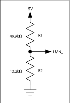
Figure 5. Line-Fault Resistor-Divider for 5V PoC.
| Condition | LMN_ Voltage (V) | Line-fault Detector Output |
| Short-to-Ground | 0 | Short-to-Ground |
| Normal Operation | 0.85 | Normal Operation |
| Open Cable | 0.85 | Normal Operation |
| Short-to-Battery (12V) | 2.04 | Open cable or short-to-battery |
12V PoC
The same resistor-divider schematic for 5V PoC is used for 12V PoC, but R1 changes to 133kΩ. Figure 6 shows this. A 133kΩ resistor is chosen to bias LMN_ at 0.85V under normal operation. Because 12V is approximately equal to a car’s battery voltage, there is no way to detect a short to the battery. A short-to-ground and normal operation read as such from the line-fault output. See Table 3 for a summary of the line-fault voltages and outputs for 12V PoC.

Figure 6. Line-fault resistor-divider for 12V PoC.
| Condition | LMN_ Voltage (V) | Line-fault Detector Output |
| Short-to-Ground | 0 | Short-to-Ground |
| Normal Operation | 0.85 | Normal Operation |
| Open Cable | 0.85 | Normal Operation |
| Short-to-Battery (12V) | 0.85 | Normal Operation |
Protection in a PoC System
In a GMSL application that uses PoC, care must be taken to prevent damage to the PoC filter, coax cable, and power supply. If the cable is ever shorted to ground, this presents a near short to the power supply, which leads to an overcurrent condition. In a 5V PoC application, a short to the battery should also be accounted for, because the overvoltage condition could damage circuitry connected to the power rail.
The MAX20087 is quad power protector that can detect and manage overvoltage, undervoltage, overcurrent and overtemperature conditions in a PoC application. The device provides protection on all the channels independently; a fault on one lane is isolated and does not impact the functionality of the others. It automatically reattempts to power the affected channel in case the fault is merely transient. The MAX20087 also provides advanced monitoring and diagnostics through an I2C interface, and it can be paired with a supervisory controller to achieve ASIL-D rating in safety-critical systems. There are four lanes of protection, perfect for a 4-camera surround view system. Figure 7 shows where the MAX20087 should be placed in a GMSL system.

Figure 7. GMSL PoC application with the MAX20087 for power protection.
Conclusion
In a GMSL application that uses PoC, an alternate line-fault circuit is required for proper fault detection. The design of this circuit depends on the PoC voltage level, typically 5V or 12V. When the cable is shorted to battery or shorted to ground, additional protection circuitry is required to prevent damage to components connected to the power rail. When used together, the MAX96705 and MAX96706 offer robust, high-speed SerDes and PoC on the same cable. Additionally, the MAX20087 can be used for protection against overcurrent and overvoltage conditions on four PoC GMSL links.