Design Note 464: High Efficiency USB Power Management System Safely Charges Li-Ion/Polymer Batteries from Automotive Supplies
Introduction
Automotive power systems are unforgiving electronic environments. Transients to 90V can occur when the nominal voltage range is 10V to 15V (ISO7637), along with battery reversal in some cases. It’s fairly straightforward to build automotive electronics around this system, but increasingly end users want to operate portable electronics, such as GPS systems or music/video players, and to charge their Li-Ion batteries from the automotive battery. To do so requires a compact, robust, efficient and easy-to-design charging system.
Complete USB/Battery Charging Solution for Use in Large Transient Environments
Figure 1 shows such a design. This complete PowerPath™ manager and battery charger system seamlessly charges the Li-Ion battery from a wide ranging high voltage or USB source.

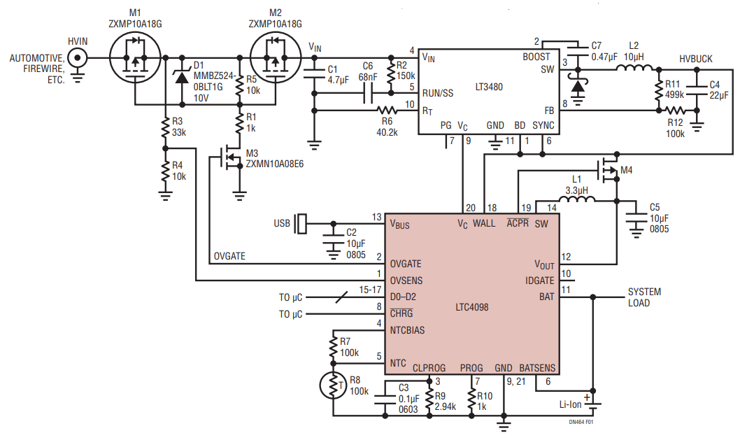
Figure 1. LTC4098 USB Power Manager/Li-Ion Battery Charger Works with an LT®3480 HV Buck Regulator to Accept Power from an Automotive Environment or Firewire System. Overvoltage Protection Protects Both ICs and Downstream Circuits.
In this circuit, the LTC4098 USB power manager/Li-Ion battery charger controls an LT3480 HV step-down regulator. The LTC4098’s Bat-Track™ feature provides a high efficiency, low power dissipation battery charger from low and high voltages alike. The Bat-Track feature controls an internal input current-limited switching regulator to regulate VOUT to approximately VBAT + 0.3V which maximizes battery charger efficiency, and thus minimizes power dissipation by operating the battery charger with minimal headroom. Furthermore, the Bat-Track feature reduces charge time by allowing a charge current greater than the USB input current limit—the switching regulator behaves like a transformer exchanging output voltage for output current.
The LTC4098 can extend the Bat-Track concept to an auxiliary regulator via the WALL and VC pins. When sufficient voltage is present on WALL, Bat-Track takes control of the auxiliary regulator’s output via the VC pin, maintaining the regulator’s output at VBAT + 0.3V.
The LTC4098 also includes an overvoltage protection function—important in volatile supply voltage environments. Overvoltage protection shuts off a protection N-channel MOSFET (M2) when the voltage at the OVSENSE pin exceeds approximately 6V. The upper limit of voltage protection is limited only by the breakdown voltage of the MOSFET, and by the current flowing into the OVSENS pin.
Overvoltage Protection Covers the Entire Battery Charger/Power Manager System
The overvoltage protection function of the LTC4098 can protect any part of the circuit. In Figure 1, the protection has been extended to the LT3480 VIN input. The overvoltage shutdown threshold has been set to 24V. This threshold provides ample margin against destructive overvoltage events without interfering with normal operation.
In Figure 1, M1 is a P-channel MOSFET that provides reverse voltage protection, whereas M2 is the overvoltage protection MOSFET, and M3 level-shifts the OVGATE output of the LTC4098.
If the HVIN voltage is less than zero, the gate and source voltages of both M1 and M2 are held at ground through R3, R4, and R5, ensuring that they are off. If the HVIN voltage is between 8V and approximately 24V, the gate of M3 is driven high via the LTC4098’s OVGATE pin. This turns on M1 and M2 by pulling their gates 7V to 10V below their sources via M3, D1, R1 and R5. With M1 and M2 on current flows from HVIN to VIN and the system operates normally.
If the HVIN input exceeds approximately 24V, the LTC4098 drives the gate of M3 to ground, which allows R5 to reduce the VGS of M1 and M2 to zero, shutting them off and disconnecting HVIN from VIN.
M1, M2 and M3 have a BVDSS of 100V, so that this circuit can tolerate voltages of approximately –30V to 100V. It will operate normally from 8V to approximately 24V. This combination is ideal for the harsh automotive environment, providing a robust, low cost and effective solution for Li-Ion battery charging from an automotive power system.
Finally, setting the OVSENS resistor divider requires some care. For an OVSENS voltage between approximately 2V and 6V, VOVGATE = 1.9 • VOVSENS. OVSENS is clamped at 6V and the current into (or out of) OVSENS should not exceed 10mA. The chosen resistor divider attenuates HVIN by a factor of 4, so M3 has sufficient gate voltage to turn on when HVIN exceeds approximately 8V. When HVIN = 100V, the current into OVSENS is just 2.25mA—well below the 10mA limit.
As shown in Figure 2, VIN is only present when HVIN is in the 8V to 24V region. Figure 3 shows a close-up centered on the load dump ramp. The ISO7637 test ramp rises from 13.2V to 90V in 5ms. There is a 220μs turn-off delay—OVGATE going low to the gates of M1 and M2—which results in an overshoot on VIN. The maximum value of this overshoot is 3.5V (VVIN(MAX) ≈ 27.5V). The magnitude of this overshoot can be calculated for different ramp rates, such that

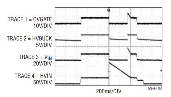
Figure 2. Overvoltage Protection Through Input Transients per ISO7637 Standards.

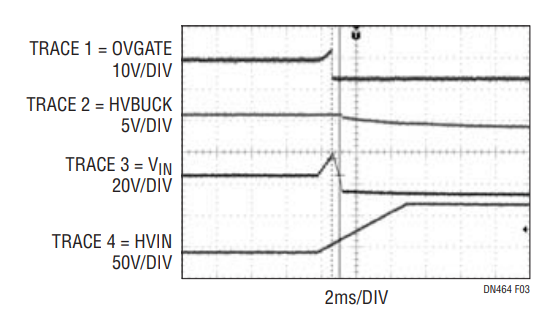
Figure 3. Closeup of Figure 2 Waveforms Showing Overshoot on HVIN.
VOVERSHOOT = ΔV/Δt • tDELAY
Where ΔV = (90V – 13.6V), Δt = 5ms, and tDELAY = 220μs, so, VOVERSHOOT = 3.36V.
If less delay, and thus less overshoot, is desired, an active turn-off circuit can reduce the delay from OVGATE to the gates of M1 and M2 to a few microseconds.
Conclusion
The LT3480 high voltage step-down regulator and LTC4098 Li-Ion/Polymer battery charger, combined with a few external components, produce a robust high performance Li-Ion charger suitable for portable electronics plugged into an automotive power source and maintain compatibility with USB power. The circuit provides all the functionality that customers expect, along with voltage protection from battery reversal and load dump transients.
Author
