Design Note 80: ESD Testing for RS232 Interface Circuits
In 1992 Linear Technology introduced the first RS232 interface circuits capable of surviving in excess of ±10kV ESD transients. Since that time, LTC has introduced more than 30 products with this level of protection. The inherent ruggedness of these products eliminates the need to use external protection devices in most applications. Not one unit has been returned from the field to Linear Technology for an ESD related failure analysis since the enhanced ESD protected devices were introduced.
The ±10kV ESD voltage rating is based on the Human Body ESD Model. When evaluated with other standard ESD test methods, the superior ESD ruggedness of LTC’s transceivers gives equally impressive results when compared to older conventional designs.
The various ESD test methodologies all share a common configuration as shown in Figure 1. A source capacitor is first charged to a high voltage, then the high voltage power supply is disconnected from the capacitor, and the capacitor is connected to the device under test through a limiting resistor. The value of the test capacitor and the limiting resistor differ among the various test standards.


Figure 1. ESD Test Standards.
The Human Body Model is the most commonly used ESD test in the United States and is the test method prescribed by Mil-Std-883. This method simulates the ESD discharge waveform seen form human contact to a piece of electronic equipment. The source capacitor is 100pF, limited by 1.5kΩ for the human body model. Linear Technology’s RS232 transceivers can withstand in excess of ±10kV when tested with the Human Body Model.
The machine model, commonly used for ESD testing in Japan, is a more severe ESD test. This model simulates metallic contact between the device under test and a charged body. The source capacitor is 200pF with no limiting resistor. The higher source capacitance and the absence of a limiting resistor causes the device under test to be subjected to more voltage, energy, and current than human body model testing. Therefore failures occur at lower test voltages with machine model than with human body model testing. LTC’s RS232 transceivers can withstand ±3.5kV when tested with the machine model.
The IEC-801 test method fits between the human body and machine methods in severity. The source capacitor is 150pF with a 330Ω limiting resistor. LTC’s RS232 transceivers pass test voltages of ±7.5kV with the IEC-801 method.
The performance of LTC’s 10kV protected RS232 transceivers to each of these test conditions is summarized in Table 1. Also included are protection levels achieved to machine model testing by including a simple RC network on the RS232 line pins. The RC network used is a “T” network formed with two 200Ω resistors and a 220pF capacitor to ground. The added resistance and capacitance are small enough to have negligible effect on RS232 signals, but provide a great increase in ESD protection at a lower cost than using TransZorbs with a diode network, which is commonly used for ESD protection. Test voltages higher than those shown in Table 1 sometimes cause device damage. The damage seen most commonly is an increase in driver output leakage with functionality failures occurring at even higher voltages.
| ESD Test Model | Driver Pin Protection | Receiver Pin Protection |
| Human Body | ±10kV | ±10kV |
| Machine | ±3.5kV | ±6kV |
| IEC-801 | ±7.5kV | ±8kV |
| Machine Model with RC Network on RS232 Pins | ±10kV | ±10kV |
ESD Transients During Powered Operation
The test methods discussed so far involve testing for permanent damage to the integrated circuit from ESD transients. In today’s portable electronics, interconnection of cables to the communications ports may occur while the equipment is operating. This makes it imperative that the circuit can tolerate the ESD transient with minimal disruption of system operation. LTC’s RS232 interface circuits can withstand 10kV ESD transients while operating, shut down, or powered down. Disruption of data transfer is unavoidable during the ESD transient event, but data transmission may resume upon the completion of the event.
Figure 2 is a scope photograph of the data transmission interruption and recovery seen when a –10kV ESD transient strikes a communications line. The test circuit of Figure 3 was used to record this event. The ESD strike is applied to the driver output of an LT1180A and the receiver input of an LT1331. The ESD transient is of too short a duration to be recorded on the photograph, but the effects of the transient can be seen by the corruption of data after the strike. The circuits require about 20μs to recover from the event, after which data transmission continues normally.

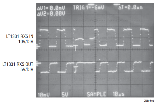
Figure 2. Effects of ESD Transient on Data Transmission Through an LT1331.

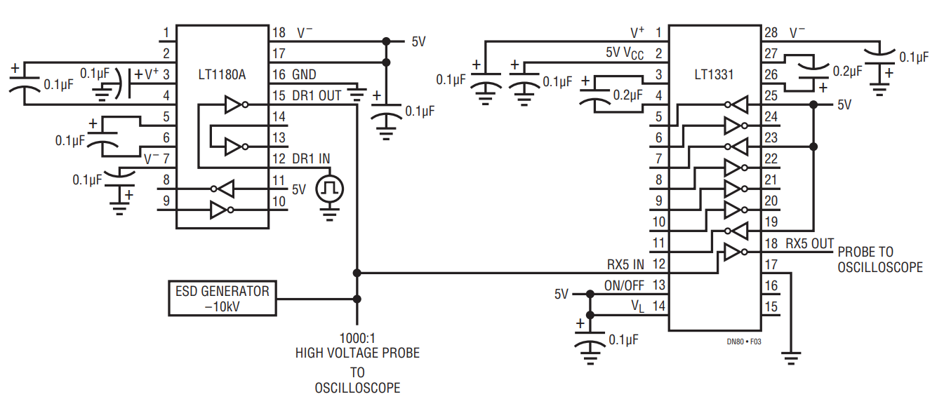
Figure 3. Operating Condition ESD Test Circuit.
Author
