Design Note 453: 4-Phase Boost Converter Delivers 384W with no Heat Sink
Introduction
High power boost converters are becoming increasingly popular among designers in the automotive, industrial and telecom industries. When power levels of 300W or more are required, high efficiency (low power loss) is imperative in the power train components to avoid the need for bulky heat sinks and forced-air cooling. Inter-leaving power stages (multiphase operation) improves efficiency and reduces ripple voltage and currents in both the input and output capacitors, allowing the use of smaller filter components.
384W Boost Converter
Figure 1 shows a 4-phase boost converter using two 2-phase LTC3862 current mode controllers configured in a master-slave configuration (as described in the LTC3862 data sheet). U1 is the master controller; it generates the clock signal that serves to synchronize the two controllers. Synchronization is achieved by connecting U1’s CLKOUT pin to U2’s SYNC pin and terminating the PLLFLTR pin of U2 with a lowpass filter. Each controller operates with a 180° phase shift between its two channels, and there is a 90° phase shift between the two controllers as defined by the state of U1’s PHASEMODE pin, to form an interleaved 4-phase system as shown in Figure 2.

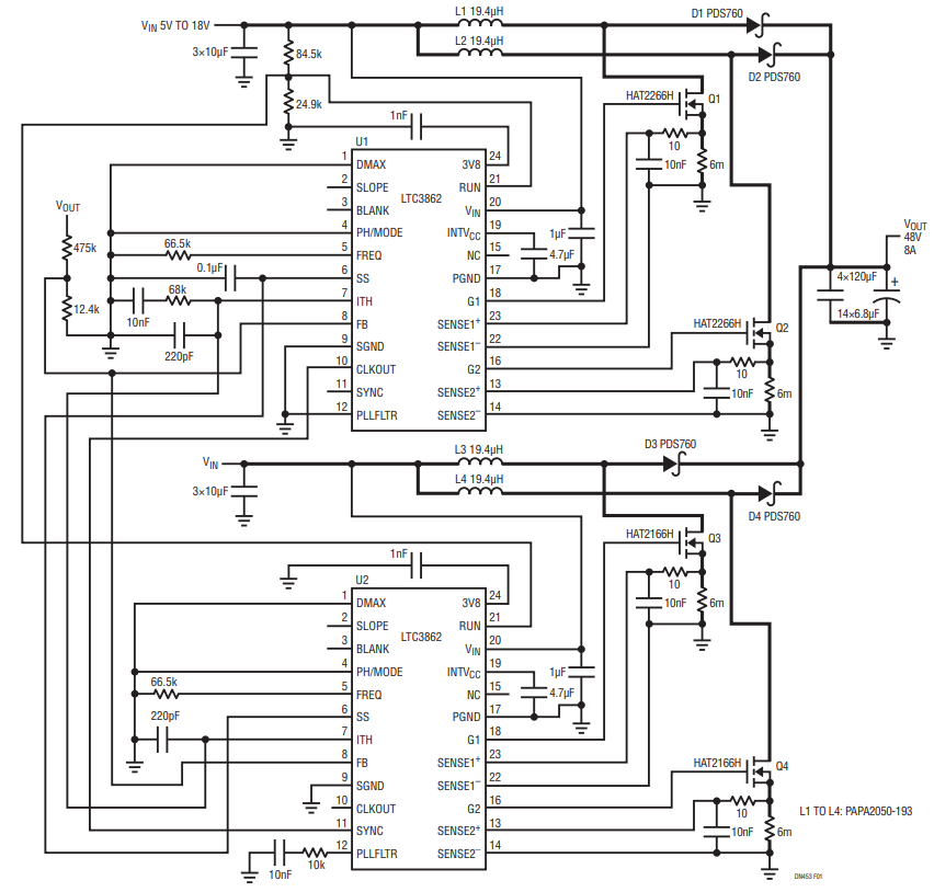
Figure 1. A 4-Phase Boost Converter Based on the LTC3862 Produces 48V at 8A from a 5V to 18V Input.


Figure 2. Timing Diagram Showing 4-Phase Operation.
The power train includes four inductors L1-L4, four MOSFETs Q1-Q4, four diodes D1-D4, along with the input and output filter capacitors. The ITH, FB, SS and RUN pins of the two controllers are connected together, which forces current share balancing and consistent start up timing between the phases, and forces both controllers to turn on at the same input voltage.
This converter can deliver 8A at 48V continuously from a 12V to 18V input. It can even support the 48V output with input voltages down to 5V, at a reduced output current. Figure 3 shows the converter efficiency above 96% for much of the load range. The transient response to a 3A load step as shown in Figure 4 has only a 100mV deviation from nominal.

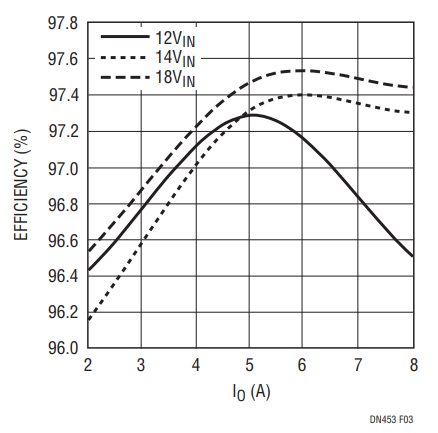
Figure 3. Efficiency vs Output Current Input Voltage for Multiple VIN.

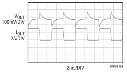
Figure 4. Transient Response for a Current Load Step from 2A to 5A.
Up to 12 power stages can be paralleled and clocked out-of-phase for even higher power applications. The LTC3862 has an input voltage range of 4V to 36V and an output voltage that is dependent upon the choice of external components, making it an excellent choice for 12V automotive high power boost converter applications such as audio amplifiers and fuel injection systems.
Conclusion
The LTC3862 2-phase controller is a powerful building block for multiphase boost converter applications that demand high efficiency, low power loss, reduced ripple voltage and currents, and have a small solution size without the need for forced-air cooling or heat sinks.
Author
