AN-1335: Temperature Measurements on the ADE7932/ADE7933 and ADE7978 Chipset
Introduction
The ADE7932/ADE7933 and the ADE7978 form a chipset dedicated to measuring 3-phase electrical energy measurement using shunts as current sensors. Both the ADE7932 and the ADE7933 contain a temperature sensor. The measurement of this sensor is available in the ADE7978. In addition, the temperature is used to compensate the gain variation in the current channel datapath.
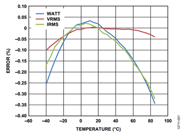
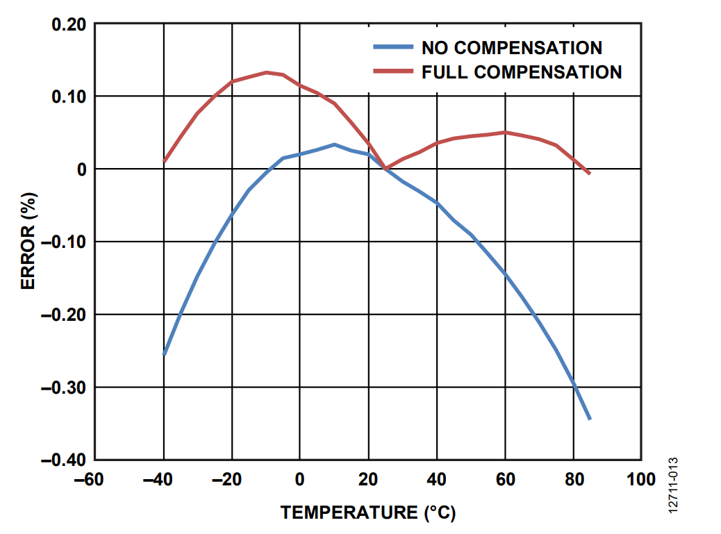
Figure 1 shows how the total active power, voltage, and current rms values on one phase vary with temperature in a typical shunt-based energy meter. The active power varies from −0.25% error at −40°C to close to 0% error at around +10°C, to −0.35% error at +85°C.
This application note first presents the factors that influence the meter performance over temperature. In addition, it presents how the temperature sensor measurements are used to compensate these factors and make the meter performance more stable with temperature. The meter accuracy margin is improved and users achieve better performance over the entire temperature range.
Energy Elements That Vary With Temperature
The energy meters are calibrated at room temperature, considered for this application note as being T0 = 25°C. When the meter temperature varies, the following meter elements vary as well:
- The shunt resistance (note that because the ADE7932/ADE7933 and the ADE7978 chipset enable the shunt-based energy metering, other current sensors like Rogowski coils and current transformers are not considered in this application note).
- The resistors of the divider sensing the phase voltages.
- The gain amplifiers placed at the analog-to-digital converter (ADC) inputs inside the ADE7932/ADE7933.
- The internal voltage reference of the ADE7932/ADE7933.
- The crystal used to clock the ADE7978.
The following sections analyze the temperature variation of each of the previous elements and provides the mathematical expressions for the variations.
Temperature Variations Analysis
Temperature Variation of the Shunt
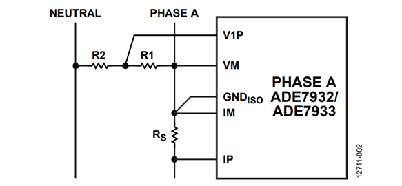
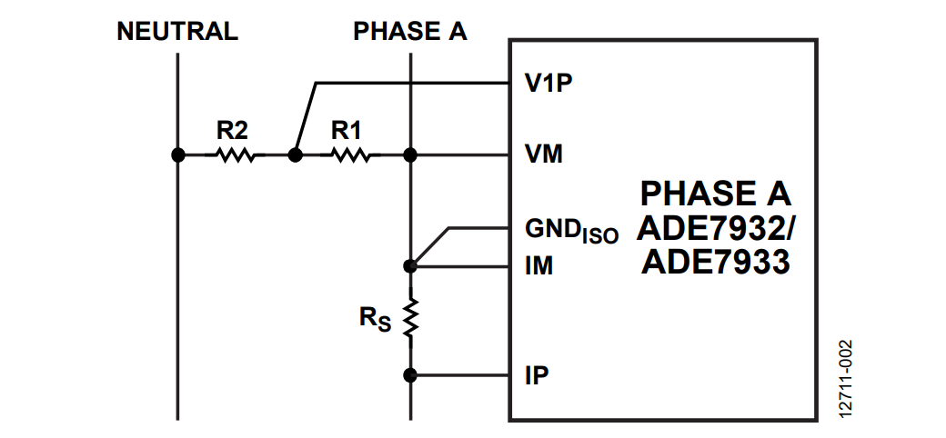
Figure 2 shows Phase A of a 3-phase energy meter that uses the ADE7932/ADE7933. A shunt senses the phase current and a resistor divider senses the phase to neutral voltage.
The shunt resistance variation with temperature is considered linear.
RS = RS,0 × (1 + αS × (T − T0)
where:
RS is the shunt resistance at temperature, T.
RS,O is the shunt resistance at temperature, T0.
αS is the temperature coefficient of the shunt.
Temperature Variation of the Resistor Divider
The resistor divider used to sense the phase voltages comprises of the R1 and R2 resistors. These resistors also vary with temperature and the variation is considered linear.
R1 = R10 × (1 + αR1) × (T − T0))
R2 = R20 × (1 + αR2) × (T − T0))
where:
R1 and R2 are the resistor values at temperature, T.
R10 and R20 are the resistor values at temperature, T0.
αR1 and αR2 are the temperature coefficients of each resistor.
The voltage measurement across resistor R1 varies with temperature as follows:

The expression shows how the temperature coefficients of the voltage divider resistors influence the voltage measurement. If the coefficients are equal, the voltage measurement does not vary with temperature (see the Deducting the Temperature Coefficient of a Voltage Divider section).
Temperature Variation of the Gain Amplifiers
The gain amplifiers placed at the current and voltage ADC inputs inside the ADE7932/ADE7933 are considered to vary linearly with temperature.
PGAI = PGAI,0 × (1 + αI × (T − T0))
PGAV = PGAV,0 × (1 + αV × (T − T0))
where:
PGAI and PGAV are the current and voltage ADC gains at temperature, T.
PGAI,0 and PGAV,0 are the gains at temperature, T0.
αI and αV are the temperature coefficients of the gain amplifiers.
Temperature Variation of the Internal Voltage Reference
The internal voltage reference varies with temperature following a second degree expression. Assume for simplicity that the temperature range of −40°C to +85°C is divided in two sections; one between −40°C and +25°C and one between +25°C and +85°C. On each section, the voltage reference varies linearly.
VREF = VREF0 × (1 + αVREF × (T − T0))
where:
VREF is the voltage of the internal voltage reference at temperature, T.
VREF0 is the voltage at temperature, T0.
αVREF is the temperature coefficient of the voltage reference.
Temperature Variation of the Crystal
The variation with temperature of the crystal frequency is assumed to be:
f = f0 × (1 + αC × (T − T0))
where:
f is the frequency of the clock produced by the crystal circuit at temperature, T.
f0 is the frequency at temperature, T0.
αC is the temperature coefficient of the crystal.
If a meter is characterized at various temperatures, all the temperature variation of these factors are fully compensated, and the energy calculations of the meter have the same accuracy across the entire temperature range.
ADE7978 Temperature Sensor Datapath
Figure 3 presents the ADC and the signal processing chain for the temperature sensor when the ADE7932/ADE7933 monitors Phase A. In a 3-phase meter using multiple ADE7932/ADE7933 devices, every chip has a temperature sensor, and the meter is capable of monitoring them independently. The temperature measurement is characterized by offset and gain errors. The offset information is calculated during the manufacturing process, and it is stored with the opposite sign into the ADE7932/ADE7933. The ADE7978 reads the offset value using the bit stream communication. It then stores the offset value into ATEMPOS, BTEMPOS, CTEMPOS, and NTEMPOS, which are the 8-bit signed registers. The offset information is shifted left by 11 bits before being added to the temperature datapath.
The gain compensation uses the ATGAIN, BTGAIN, CTGAIN, and NTGAIN 24-bit signed temperature gain registers that change the temperature waveform by ±100%.
The result of the temperature calculation is stored into the ATEMP, BTEMP, CTEMP, and NTEMP 24-bit signed registers. These values are then used during the temperature compensation of the current channel signal path as presented in Figure 4.
The temperature compensation factor 1 − TEMPCO × (xTEMP − xTEMP0), x = A, B, C, N, corrects the current waveforms coming out of the high-pass filter (HPF).
Compensating the Temperature Variation of Current Channel Components
The current channel signal path of the ADE7932/ADE7933 and the ADE7978 is presented in Figure 4. The elements of this path that vary with the temperature are the shunt connected between the IP and IM pins, the amplifier gain of the ADC, and the voltage reference.
The following expression compensates the temperature variation of the current measurement datapath:
ADCI,0 = ADCI × (1 + (αVREF + αI − αS) × (T − T0))
See the Deducting the Current ADC Output Function of Temperature section for details on how this expression was deducted.
If the TEMPCO register of the ADE7978 is set to account for the αVREF + αI − αS factor, the temperature variation of the elements composing the current channel is compensated.
There are two methods of implementing this compensation: Method A and Method B. Method A leaves the gain compensation registers ATGAIN, BTGAIN, CTGAIN, and NTGAIN at their default value of 0 and calculates the temperature in submultiples of degrees Celsius (°C) in the microcontroller (see the Method A: Microcontroller Computes the Temperature section). Method B adjusts the gain compensation registers to obtain the temperature in submultiples of degrees Celsius (°C) in the ADE7978 (see the Method B: ADE7978 Computes the Temperature section).
Examples are shown for calculating the TEMPCO register with both methods when typical coefficients are used. Note that using typical values compensates for the temperature induced errors only for typical meter components. See the Note of Caution About Using Typical Temperature Coefficients section for more details.
Method A: Microcontroller Computes the Temperature
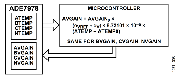
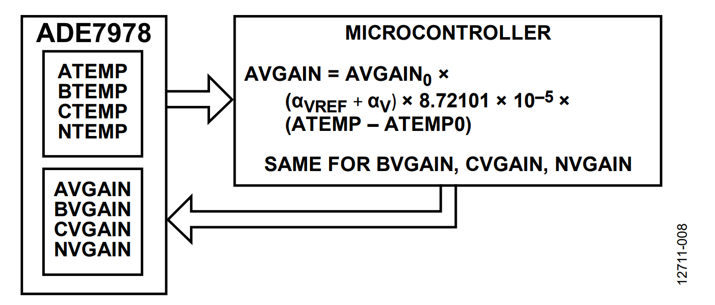
Method A (see Figure 5) consists of the microcontroller computing the temperature by implementing the following formula:
Temperature (°C) = 8.72101 × 10⁻⁵ × TEMP − 306.47
where TEMP is the content of the temperature registers ATEMP, BTEMP, CTEMP, or NTEMP.
The ATGAIN, BTGAIN, CTGAIN, and NTGAIN registers are left at their default value of 0.
To increase the resolution of the calculation, write the formula as follows to provide results in a submultiple of degrees Celsius, 10−3 °C:
Temperature (10−3°C) = 8.72101 × 10⁻² × TEMP − 306,470
The ATEMP0, BTEMP0, CTEMP0, and NTEMP0 registers are set to the ambient temperature reading obtained in the ATEMP, BTEMP, CTEMP, and NTEMP registers.
The 24-bit signed TEMPCO register contains the temperature coefficient that must be compensated.
Temperature (10−3°C) = 8.72101 × 10−2 × 3,796,835 − 306,470 = 24,652
This means the temperature is 24.6°C.
The isolated side of the ADE7932/ADE7933 isolated ADCs is identical to the isolated side of the ADE7912/ADE7913. The cumulative histograms presented in the Typical Performance Characteristics section of the ADE7912/ADE7913 data sheet are also representative of the ADE7932/ADE7933. The histograms show that a typical production lot presents a typical temperature coefficient of approximately αVREF + αI = −6 ppm/°C for temperatures between −40°C and +25°C.
When the temperature is between 25°C and 85°C, a typical production lot presents a typical temperature coefficient of approximately αVREF + αI = −12 ppm/°C.
For example, if the shunt is made of manganin and has a typical temperature coefficient of 50 ppm/°C between −40°C and +25°C and of 8 ppm/°C between +25°C and +85°C, the typical temperature variation of the shunt and of the current channel of the ADE7932/ADE7933 can be compensated using the TEMPCO register of the ADE7978. (Note that every shunt product has its own typical temperature coefficients. The numbers in this application note are used as implementation examples. Use the temperature coefficients provided by the manufacturer of the particular shunt used in the meter.)
For the −40°C to +25°C temperature range:
TEMPCO = round(−(−6 + 50) × 10−6 × 8.72101 × 10−5 × 246)
where TEMPCO = −270,022 = 0xFBE13A.
For the 25°C to 85°C temperature range, initialize the TEMPCO register with the following value:
TEMPCO = round(−(−12 + 8) × 10−6 × 8.72101 × 10−5 × 246)
where TEMPCO = 24,547 = 0x5FE3.
Method B: ADE7978 Computes the Temperature
Method B (see Figure 6) consists of the ADE7978 providing the temperature measurement result in the ATEMP, BTEMP, CTEMP, and NTEMP registers already expressed in submultiple of degrees Celsius, 10−3°C. The gain compensation registers, ATGAIN, BTGAIN, CTGAIN, and NTGAIN, are set to 9,120,179 = 0x8B29B3, which is the 24-bit signed representation of 8.72101 × 10⁻² − 1 = −0.9127899. The microcontroller then subtracts 306,470 from the ATEMP, BTEMP, CTEMP, and NTEMP registers to obtain the temperature in 10−3°C units.
The 24-bit signed TEMPCO register contains the temperature coefficient that must be compensated.

The ATEMP0, BTEMP0, CTEMP0, and NTEMP0 registers are set to the ambient temperature reading obtained in the ATEMP, BTEMP, CTEMP, and NTEMP registers. For example, at the ambient temperature, ATEMP = 3,796,835 when ATGAIN = 0.
Having initialized the gain register, ATGAIN, at 9,120,179, the ADE7978 computes ATEMP = 331,122. The microcontroller then subtracts 306,470 to obtain 24,652, which is 24.6°C.
The ATEMP0 register is then set to 331,122.
Use the same shunt characteristics introduced in the Method A: Microcontroller Computes the Temperature section. The shunt is made of manganin and has a typical temperature coefficient of 50 ppm/°C between −40°C and +25°C and of 8 ppm/°C between +25°C and +85°C.
For the −40°C to +25°C temperature range, initialize the TEMPCO register with:

where TEMPCO = −3,096,224 = 0xFD0C15F.
For the 25°C to 85°C temperature range, initialize the TEMPCO register with another value.

where TEMPCO = 281,475 = 0x44B83.
Compensating the Temperature Variation of Voltage Channel Components
The voltage channel datapath of the ADE7932/ADE7933 and the ADE7978 is presented in Figure 7. The elements of this path that vary with temperature are the voltage divider connected between the V1P and VM pins, the amplifier gain of the ADC, and the voltage reference.
The expression used to compensate the temperature variation of the voltage measurement datapath is:
ADCV,0 = ADCV × (1 + (αVREF + αV − αR1 + αR2) × (T − T0))
See the Deducting the Voltage ADC Output Function of Temperature section for details on how this expression was deducted.
The ADE7978 does not have any special correction path for this channel; therefore, the microcontroller has to calculate the correction factor based on the temperature sensor measurement done in the ADE7933 and update in real time the AVGAIN, BVGAIN, CVGAIN, and NVGAIN registers.
Examples are shown for implementing this compensation in the microcontroller using typical temperature coefficients. Note that using typical values compensates the temperature induced errors only for the energy meter components that have typical temperature coefficients. See the Note of Caution About Using Typical Temperature Coefficients section for more details.
Suppose that the meter has been calibrated at ambient temperature, and the AVGAIN, BVGAIN, CVGAIN, and NVGAIN registers have been set respectively to AVGAIN0, BVGAIN0, CVGAIN0, and NVGAIN0.
For example, on Phase A, after the gain calibration is executed, the ADC output is corrected by the 1 + AVGAIN0 factor.
ADCV` = ADCV × (1 + AVGAIN0)
Applying the temperature corrections means:
ADCV` = ADCV × (1 + AVGAIN0) ×
(1 + (αVREF + αV − αR1 + αR2) × (T − T0))
ADCV` ≅ ADCV ×
1 + AVGAIN0 + (αVREF + αV − αR1 + αR2) × (T − T0
To correct the temperature variation of the voltage channel components, update the gain calibration register AVGAIN with:
AVGAIN = AVGAIN0 + (αVREF + αV − αR1 + αR2) × (T − T0)
The isolated side of the ADE7932/ADE7933 isolated ADCs is identical to the isolated side of the ADE7912/ADE7913. The cumulative histograms presented in the Typical Performance Characteristics section of the ADE7912/ADE7913 data sheet are also representative of the ADE7932/ADE7933. The histograms show that the internal voltage reference and the voltage ADC gain have an overall temperature coefficient that varies between −65 ppm/°C and +65 ppm/°C. A typical production lot presents a typical temperature coefficient of approximately αVREF + αV = −10 ppm/°C for temperatures between −40°C and +25°C.
When the temperature is between 25°C and 85°C, a typical production lot presents a typical temperature coefficient of approximately αVREF + αV = −6 ppm/°C.
If the voltage divider resistors have the same typical temperature coefficient, then αR1 = αR2.
If the method presented in the Method A: Microcontroller Computes the Temperature section is used (see Figure 8), T0 is the ATEMP register value measured at the calibration time, ATEMP0. T is the ATEMP register value measured after the temperature inside the meter, ATEMP.
The new value of AVGAIN is:
AVGAIN = AVGAIN0 + (αVREF + αV) × 8.72101 × 10⁻⁵ × (ATEMP − ATEMP0)
To calculate this for temperatures between −40°C and +25°C, first compute:
(αVREF + αV) × 8.72101 × 10−5 =
round(−10 × 10−6 × 8.72101 × 10−5 × 246) = −61,369
Then do the following:
AVGAIN = AVGAIN0 − 61,369 × (ATEMP − ATEMP0)
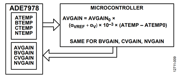
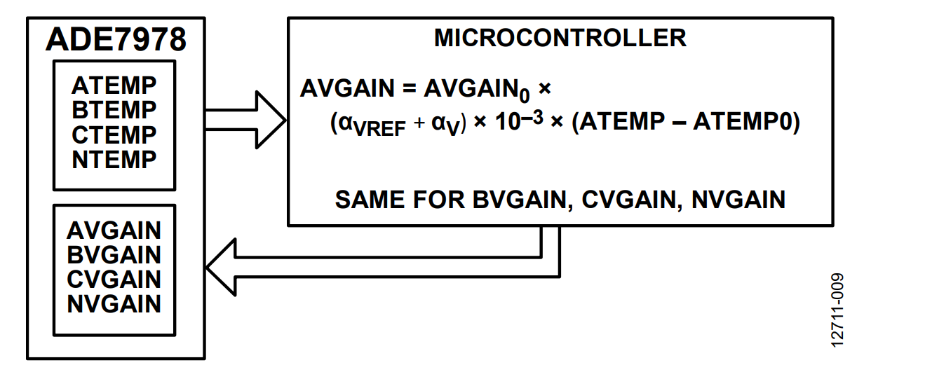
If the method presented in the Method B: ADE7978 Computes the Temperature section is used (see Figure 9), the ADE7978 registers ATEMP0 and ATEMP are expressed in 10−3 °C. The ATEMP0 register is set to the ambient temperature reading obtained in the ATEMP register.
The new value of AVGAIN is:
AVGAIN = AVGAIN0 + (αVREF + αV) × 10−3 ×
(ATEMP − ATEMP0)
To calculate this for temperatures between −40°C and +25°C, first compute:
(αVREF + αV) × 10−3 = round(−10 × 10−6 × 10−3 × 246) = −703,687
Then do the following:
AVGAIN = AVGAIN0 − 703687 × (ATEMP − ATEMP0)
For temperatures between 25°C and 85°C, compute
(αVREF + αV) × 10−3 = round(−6 × 10−6 × 10−3 × 246) = −422,212
Then do the following:
AVGAIN = AVGAIN0 − 422,212 × (ATEMP − ATEMP0)
Compensating the Temperature Variation of the Crystal
The temperature variation of the frequency of the crystal translates into an error of the time base over which the energy is accumulated. The following expression compensates the temperature variation of the frequency of the crystal:
E0 = E × (1 + αC × (T − T0))
See the Effects to the Energy Calculation When Varying the Crystal with Temperature section for details on how this expression was deducted.
This correction is equivalent to updating the gain compensation registers used in the instantaneous active, reactive, and apparent powers datapaths. The ADE7978 does not have any special correction path for these registers. The microcontroller has to calculate the correction factors based on the temperature sensor measurement done in the ADE7933 and update in real time the APGAIN, BPGAIN, and CPGAIN registers.
Suppose that the meter has been calibrated at ambient temperature, and the APGAIN, BPGAIN, and CPGAIN registers have been set respectively to APGAIN0, BPGAIN0, and CPGAIN0.
For example, on Phase A, after the gain calibration is executed, the active energy outputregister, AWATTHR, is corrected by the 1 + APGAIN0 factor.
AWATTHR` = AWATTHR × (1 + APGAIN0)
Applying the temperature corrections results in the following:
AWATTHR` = AWATTHR × (1 + APGAIN0) ×
(1 + α0 × (T − T0))
AWATTHR`≅AWATTHR ×
(1 + APGAIN0 + αC × (T − T0
)Correcting the temperature variation of the crystal means updating the gain calibration register APGAIN with:
APGAIN = APGAIN0 + αC × (T − T0)
Suppose that APGAIN0 has already been obtained at calibration, and the crystal has 1 ppm/°C temperature coefficient. Note that every crystal product has its own typical temperature coefficient. The 1 ppm/°C coefficient is used as an implementation example. Use the temperature coefficient provided by the manufacturer of the particular crystal used in the meter.
If the method presented in the Method A: Microcontroller Computes the Temperature section is used, T0 is the ATEMP register value measured at the calibration time, ATEMP0. T is the ATEMP register measured after the temperature inside the meter.
The new value of APGAIN is:
APGAIN = APGAIN0 + αC × 8.72101 × 10⁻⁵ ×
(ATEMP − ATEMP0)
To calculate this, first compute:
αC × 8.72101 × 10−5 =
round(10−6 × 8.72101 × 10−5 × 246) = 6136
Then do the following:
APGAIN = APGAIN0 + 6136 × (ATEMP − ATEMP0)
If the method presented in the Method B: ADE7978 Computes the Temperature section is used, the ADE7978 registers ATEMP0 and ATEMP are expressed in 10−3°C. The ATEMP0 register is set to the ambient temperature reading obtained in the ATEMP register.
The new value of APGAIN is:
APGAIN = APGAIN0 + αC × 10−3 × (ATEMP − ATEMP0)
To calculate this, first compute:
αC × 10−3 = round(10−6 × 10−3 × 246) = 70,369
Then do the following:
APGAIN = APGAIN0 + 70,369 × (ATEMP − ATEMP0)
Note that the other elements of the ADE7933 that vary with temperature (internal voltage reference, current and voltage ADC gains, shunt, and voltage divider) are compensated in the current and voltage datapaths. Only the crystal frequency variation with temperature remains to be compensated by the APGAIN, BPGAIN, and CPGAIN registers. If no compensation is done in the current and voltage datapaths, the compensation of all elements must be done using the APGAIN, BPGAIN, and CPGAIN registers. In this case, the following expression compensates the temperature variation:
E0 = E × (1 + (αC + 2 × αVREF + αI + αV − αS − αR1 + αR2) × (T − T0))
See the Effects to the Energy Calculation When Varying the Temperature of All Elements section for details on how this expression has been deducted.
The implementation procedure of this expression is identical to the procedure recommended in dealing with the crystal. The APGAIN, BPGAIN, and CPGAIN registers are corrected using the following expression:
APGAIN = APGAIN0 +
(αC + 2 × αVREF + αI + αV − αS − αR1 + αR2) × (T − T0)
Note of Caution About Using Typical Temperature Coefficients
Using typical temperature coefficients compensates the temperature induced errors only when typical ADE7932/ADE7933 devices, shunts, resistors, and crystals are mounted simultaneously in the meter. For components that do not have typical temperature coefficients, the approach presented in the previous sections may improve the compensation results or may make them worse, depending on the component position on the distribution curve of the temperature coefficient.
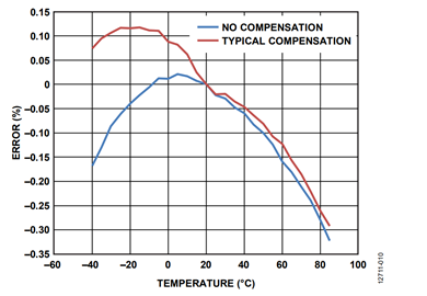
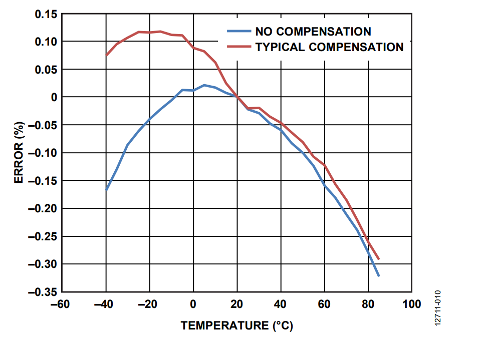
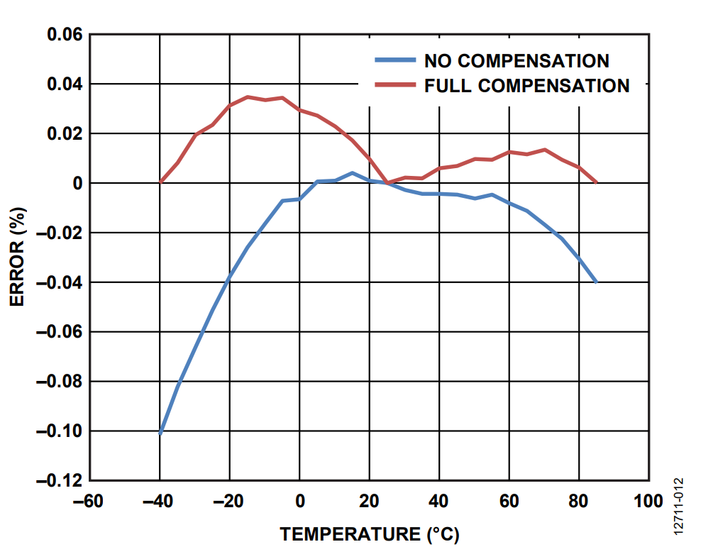
Figure 10 shows the experimental results of the temperature compensation of the current channel. The AIRMS measurement of the ADE7978 was gain calibrated at 25°C using the AIGAIN register. The board, together with the shunt, was set at temperatures between −40°C and +85°C in 5°C increments, and the no compensation points were obtained. When the temperature compensation was done using the typical coefficients (typical compensation points in Figure 10), the performance at −40°C improved from −0.17% to +0.6%, while the performance at +85°C did not improve at all.
Findings
Experimental Results
To verify the performance of a meter using the isolated energy metering chipset ADE7932/ADE7933/ADE7978 across the entire temperature range, an ADE7933/ADE7978 evaluation board was used. A 200 µΩ shunt was used as the current sensor. The phase current was set as a 55 A rms sinusoid. The 55 A rms represents 50% of the rms value of a sinusoidal current that produces a peak equal to 31.25 mV, the current ADC input range. The phase voltage was set as a 175 V rms sinusoid. The 175 V rms represents 50% of the rms value of a sinusoidal voltage that produces a peak equal to 500 mV, the voltage ADC input range.
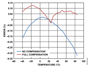
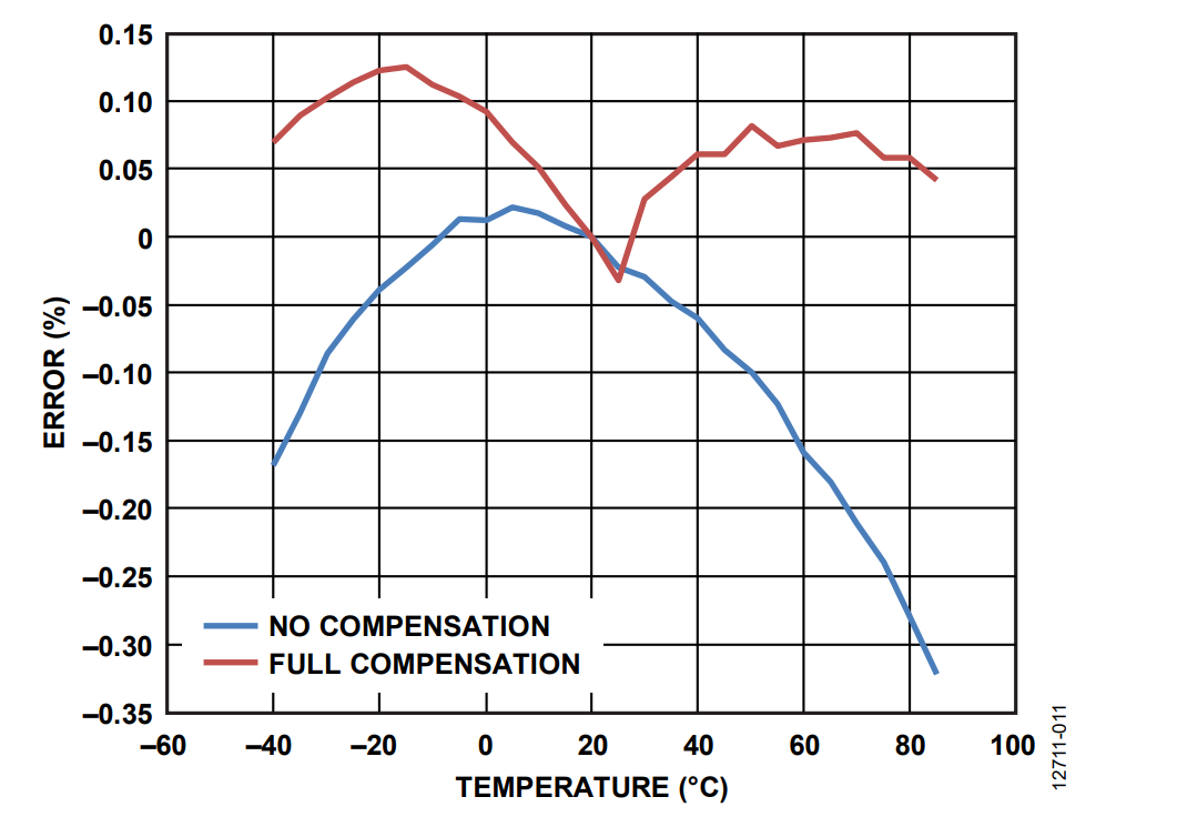
The AIRMS measurement of the ADE7978 was gain calibrated at 25°C using the AIGAIN register. Then, the board, together with the shunt, was set at −40°C and the Phase A current rms value was measured. The temperature was then increased in 5°C steps up to 85°C, and at each point, the rms measurement was taken. The errors relative to the expected value are shown in blue in Figure 11 (it is the same no compensation blue line from Figure 10).
The temperature coefficient was computed for the value obtained at −40°C and used to compensate the temperature variation of the current channel for all temperatures between −40°C and +25°C. Then, the temperature coefficient was computed at 85°C and used to compensate the temperature variation of the current channel for all temperatures between 30°C and 85°C. The full compensation red curve in Figure 11 presents the rms errors over −40°C and +85°C with the compensation.
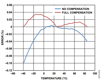
The process was repeated for the voltage rms and the total active power. The before and after compensation curves are shown in Figure 12 and Figure 13. These figures, together with Figure 11, show how the performance over temperature of the ADE7932/ADE7933/ADE7978 chipset is improved when the meter is characterized over temperature.
Figure 11, Figure 12, and Figure 13 show that after compensation, the errors across the temperature range are smaller relative to the initial uncompensated results.
Conclusion
This application note presented the meter components that introduce a variation with temperature of the energy metering quantities. The typical temperature coefficient values of each component compensates the temperature variation. One problem, however, is that the entire population of each component presents a distribution around the typical values. This means that when the typical values are used for compensation, some meters are well compensated and undergo an improved temperature response. However, some suffer a worsened response.
The following is an alternative approach to fixing this problem:
- Bring the meter at the lowest and highest temperatures for which the specification is required.
- Measure the current rms, voltage rms, and energy values.
- Calculate two temperature coefficients, one for each extremity of the temperature range.
- Use these coefficients for temperature compensation over the entire temperature range.
Calculations
Deducting the Temperature Coefficient of a Voltage Divider
The following is the voltage divider (resistors R1 and R2 from Figure 2) function of the temperature coefficients:

where:
R10 and R20 represent the values of R1 and R2 at temperature, T0.
αR1 and αR2 represent the temperature coefficients of R1 and R2 resistors.
It is assumed that the factor:

is very small and is approximated as being equal to:

Then, introducing this term into the previous voltage divider expression, we obtain the following:
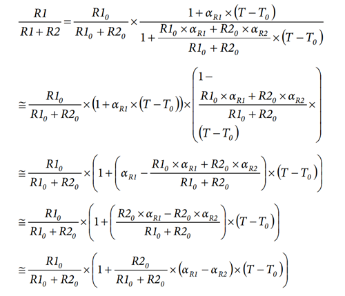
Usually R20 is much greater than R10, therefore:
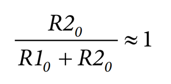
The final expression of the voltage divider variation with temperature is:

Deducting the Current ADC Output Function of Temperature
An expression of the current ADC output (ADCI) after passing through the digital low-pass filter (LPF) is:

where:
RS is the shunt that senses the current (I) (see Figure 2).
VFS is the maximum input voltage of the ADC. It is equal to a factor k multiplied by the internal voltage VREF and the gain amplifier PGAI.
Introducing the temperature variation, the current ADC output is:

where:
RS,0, VREF0 and PGAI,0 represent the values of RS, VREF and PGAI at temperature, T0
αS, αVREF and αI represent the temperature coefficients of RS, VREF and PGAI.
Considering αVREF × α1 × (T − T0)2 ≅ 0, the expression of the current ADC variation with temperature may be simplified as follows:
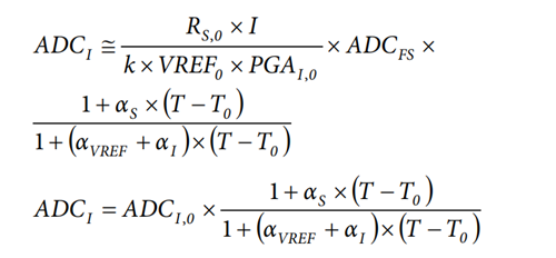
where ADCI,0 is the current ADC output at temperature, T0.

To compensate the temperature variation and obtain continuously the current ADC output (ADCI,0) measured at temperature T0, multiply ADCI by the inverse of the temperature factor.

Because αS × (T &minnus; T0) << 1, rewrite the expression as:
ADCI,0 = ADCI × (1 + (αVREF + αI) × (T − T0)) ×
(1 − αS × (T − T0))
Considering the following:
(αVREF + α1) × αS × (T − T0)2 ≅ 0
The expression used to compensate the temperature variation of the shunt and of the current ADC is:
ADCI,0 = ADCI × (1 + (αVREF + αI − αS) × (T − T0))
Deducting the Voltage ADC Output Function of Temperature
The following expression is the voltage ADC output (ADCV) after passing through the digital low-pass filter (LPF):
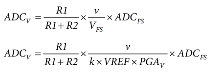
where:
R1 and R2 are the resistors of the voltage divider that senses the voltage, v (see Figure 2).
VFS is the maximum input voltage of the ADC. It is equal to a factor k multiplied by the internal voltage VREF and the gain amplifier PGAV.
Introducing the temperature variation, one can determine that the voltage ADC output is:

where:
R10, R20, VREF0, PGAV,0 represent the values of R1, R2, VREF, and PGAv at temperature, T0.
αR1 , αR2 ,αVREF and αV represent the temperature coefficients of R1, R2, VREF and PGAV.
Considering the following:
αVREF × αv × (T − T0)2 ≅ 0
Thus,

where ADCV,0 is the voltage ADC output at temperature, T0:

To compensate the temperature variation and to continuously obtain the voltage ADC output (ADCV,0) measured at T0, one must multiply ADCV by the inverse of the temperature factor.

Because (αR1 − αR2) × (T − T0) << 1, rewrite the expression as:
ADCV,0 = ADCV × (1 + (αVREF + αV) × (T − T0)) ×
(1 − (αR1 − αR2) × (T − T0))
Considering the following:
αVREF + αv) × (αR1 − αR2) × (T − T0)2 ≅ 0
It is possible to obtain the expression used to compensate the temperature variation of the voltage divider and of the voltage ADC.
ADCV,0 = ADCV × (1 + (αVREF + αV − αR1 + αR2) × (T − T0))
Effects to the Energy Calculation When Varying the Crystal with Temperature
If the instantaneous power is constant, the energy accumulated over N clock periods is:

where:
f is the clock frequency.
f0 is the clock frequency at temperature, T0.
αC is the temperature coefficient of the crystal.
P is the instantaneous power.
E is the energy.
 is the energy value obtained when the frequency.
of the clock is equal to the f0.
To compensate for the temperature variation and obtain an energy value unaffected by the frequency variation of the crystal with temperature, one must multiply the energy calculation by the inverse of the temperature factor.
E0 = E × (1 + αC × (T − T0))
Effects to the Energy Calculation When Varying the Temperature of All Elements
All instantaneous power calculations of the ADE7978 are fundamentally a measure of the multiplication between the instantaneous values of the current and voltage ADC outputs.
P = ADCI × ADCv
The energy accumulated over N clock periods is:

where f is the clock frequency.
Based on the findings of the other calculations, the variation of the energy function of temperature is:

where:
ADCI,0 and ADCV,0 are the current and voltage ADC outputs at temperature, T0.
f0 is the clock frequency at temperature, T0.
αC, αS, αR1, αR2, αVREF, αI, αV are the temperature coefficients of respectively, the crystal, the shunt, the resistors R1 and R2 of the voltage divider, the voltage reference, and the current and voltage gain amplifiers.
Considering αS × (αR1 − αR2) × (T − T0)2 ≅ 0 and:
(αVREF + α1) × (αVREF) + αv) × (T − T0)2 ≅ 0, the variation of the energy function of temperature is:

where the following equation represents the energy value obtained at temperature, T0:

To compensate the temperature variation and continuously obtain the energy measured at T0, multiply E by the inverse of the temperature factor.

Because (αS + αR1 − αR2) × (T − T0) << 1, rewrite the expression as:
E0 = E × (1 + (αC + 2 × αVREF + αI + αV − αS − αR1 + αR2) × (T − T0))
