AN-025: DC Motor Control with TMC4671
The TMC4671 hardware controller performs Field Oriented Control (FOC) for two-phase stepper motors and for three-phase permanent magnet synchronous motors (PMSM) and it supports DC motor control. Why TMC4671 for DC motor servo control? The TMC4671 provides hardware closed loop torque control, velocity control, and position control even for DC motors decoupling motor control from application.
DC Motor Closed Loop Control
When using the TMC4671 for closed loop DC motor control, one current controller is used for torque control while the coordinate transformations required for FOC are skipped. Servo control functions as velocity control and position control of DC motors are similar to two-phase stepper motors and three-phase permanent magnet synchronous motors. The TMC4671 hardware provides an ADC engine, an encoder engine, PI controllers for closed loop current control, velocity control, position control, and a PWM engine usable in a unified way for DC motor control.
DC Motor Control Configuration
The base for torque control of a DC motor enfolds configuration of analog digital converter ADC for current measurement, optional PWM adjustment, and the essential parameterization of P parameter and I parameter of the PI closed loop current controller. DC motor control of the TMC4671 is selected by the dedicated DC motor type control mode.
A proper setup of closed loop current control is essential when using closed loop velocity control. For velocity control, one needs to set up some parameters of the position sensor. The TMC4671 uses a position sensor to measure the speed. A proper setup of closed loop current control together with a proper setup of velocity control is essential when using position control.
The TMC4671 is equipped with integrated limiters to configure save operation area even on faults caused by wrong configuration. These limiters are useful, especially during initial setup.
An important fault that might damage a motor or a power supply is a wrong sign of current measurement. With that, the current controller opens the PWM duty cycle up to 100%. With a programmable limiter, one can clip the PWM duty cycle to save operation where the resulting current is limited be the inner resistance of the motor. On the other side, this limiter limits the reachable performance of the motor.
TMC4671 Evaluation Boards for Application Note
The evaluation kit used as exemplary hardware platform configuration for this application note is Landungsbruecke v1.2 + TMC4671-EVAL v.1.1 + TMC-UPS-10A/70V-EVAL v.1.1 + DC Motor resp. a coil with an inductance L = 1 mH and resistance of 1 Ohm with a 24 V power supply. A coil is useful for emulating a blocked DC motor for initial setup of the closed loop current regulation.
DC Motor Turning
Why initially turn the DC motor open loop? Initially, one needs to turn the motor open loop to check the current measurement for the motor to check the association between ADC channel selection and DC motor terminals and to adjust the ADC scaling parameter and the ADC offset parameter.
To turn a DC motor open-loop, one just needs to apply a supply voltage VM to the DC motor. Together with PWM the effective voltage U applied to the motor is U = Vm * PWMdutyCycle[%]. For DC motor mode, the PWM duty cycle of the TMC4671 is programmed via UQ_EXT value of register UQ_UD_EXT where the UQ_EXT is a 16 bit signed value with the sign representing the sign of the effective voltage applied to the motor. The Upwm[V] = VM[V] * UQ_EXT[-32767 to 0, 0 to +32767] is the effective voltage between the terminals of the PWM power stage.
Select DC Motor Type
Choose Motor Type = 0 for DC motor control. The PWM is choppering even in Motor Type = 0 mode but with zero effective coil voltage between terminals. This is to support boot-strapping charge pump of gate drivers.
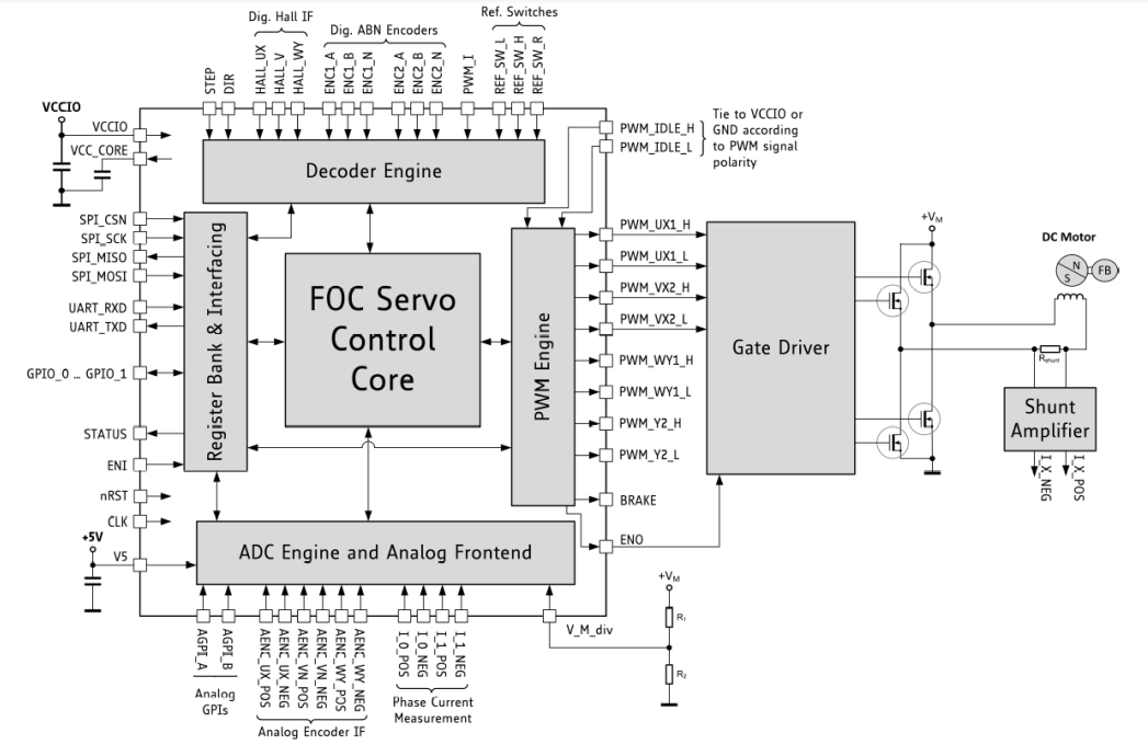
Choose Motor Type = 1 for DC motor with number of pole pairs NPP = 1. The number of pole pairs is not relevant for DC motor control but with that, electrical angles are same as mechanical angels when measuring angles with encoders. The motor type = 0 configures the PWM assigning the terminals U and V for the DC motor (Figure 1).

0: no motor (PWM choppers in zero voltage mode)
1: DC motor
2: two-phase permanent magnet synchronous motor (stepper motor)
3: three-phase permanent magnet synchronous motor (PMSM, brushless motor)
DC Motor Turning – Open Loop for Current Measurement Setup
For open loop motor turning, one applies PWM with a programmed duty cycle for the two half bridges with the DC motor connected between the terminals U and V. The supply voltage together with the PWM duty cycle determines the speed of motor.
For FOC2 and FOC3, the UD_EXT is used to turn the motor open loop to determine the D direction of the current. In contrast to FOC3 and FOC2, for the DC motor - named FOC1 because the motor mechanically make FOC by its mechanical commutator brushes - the UQ_EXT is used turn the DC motor because the current through the DC motor generates torque similar to the torque generating current IQ in case of FOC2 and FOC3.
DC Motor Turning – Closed Loop with PI Regulator
For closed loop current control, a PI regulator controls the current by measuring the actual current and regulating the difference to the desired target current to zero. Initially, the P and I parameter of the PI regulator should be set to zero.
First, the P parameter should be incremented with temporarily set I = 0 during determination of P parameter until the PI regulator reaches half of the desired target current. With a determined P parameter, the parameter I should be incremented until the PI regulator reaches the full desired target current. With that, one has an initial setup for the current regulation. The magnitude of the parameter I determines how fast the PI current regulator reaches the desired target current. A too large parameter I causes control loop oscillations.
A good initial choice of I parameter for PI current controller setup is an I parameter that results in 1/8 of current change in time dII/dt comparted to the current change in time dIL/dt = UL/L of the inductance L of the motor while the P is temporarily set to 0 for determination of I parameter. To give an example: At t=0, a coil with L = 1 mH, and supply voltage 24V gives a dIL/dt = 24000A/s. If a TMC4671 with TMC-UPS-10A/70V power stage and 24V supply voltage gives and current changes in time of 3A/s for I=1 one could initially set I = 1/8 * 24000A/3A = 1000.
Setup ADC for Measurement of Current
The TMC4671 supports two parallel sampling ADC channels for motor current measurement. For DC motor current measurement, the first channel ADC_I0_RAW is associated to measure the current of the DC motor. Some base ADC parameter need to be initialized.
ADC Delta Sigma Parameter – Initial Base Parameters
The TMC4671 is equipped with internal Delta Sigma ADCs. The Delta Sigma ADC of the TMC4671 provide programmable filtering of input signals to adjust resolution vs. speed. The Delta Sigma ADCs are organized in two groups to enable different resolutions and speeds for these groups. Group A is for primarily for current measurement. Group B is primarily for processing of analog encoder signals. The following default settings fit for most standard applications and are useful as initial parameter settings. Those settings are initialized by the TMCL-IDE Wizard, by Clicking on Default Settings.
| ADDR | Address Name | Data | Function |
| 0x04 | dsADC_MCFG_B_MCFG_A | 0x00130013 | ADC configuration group B and A |
| 0x05 | MCLK_A | 0x20000000 | Delta Sigma Clock A |
| 0x06 | MCLK_B | 0x00000000 | Delta Sigma Clock B off |
| 0x07 | dsADC_MDEC_B_MDEC_A | 0x01000100 | Deciamtion for B & A |
| 0x0A | ADC_I_SELECT | 0x14000300 | Select ADC channel for DC motor |
| 0x1B | MOTOR_TYPE_N_POLE_PAIRS | 0x00010001 | DC motor type, number of pole pairs |
| 0x24 | UQ_UD_EXT | 0x00000000 | UQ_EXT for PWM duty cycle, 1st zero |
| 0x63 | ZMODE_RAMP_MODE_MOTION | 0x00000008 | classical PID type, UQ_UD_EXT mode |
| Z | Z | Z | Z |
Adjust ADC Offsets and ADC Scaling and Sign
The integrated ADCs deliver unsigned raw ADC values (ADC_RAW) within the 16 bit unsigned range 0 to 65535. The PI current controller needs scaled and offset corrected signed ADC values within the 16-bit signed range of -32767 to +32767 to perform closed loop current control. Similar to FOC2 and FOC3, it is essential to set correct ADC scale parameter, and correct ADC offset parameter for real time correction by the integrated ADC scaler and ADC offset compensator.
Closed loop current control of DC motor needs correct association between applied voltage and measured current. For positive voltage UQ, a positive current IQ needs to be measured. For negative voltage -IQ, a negative current –IQ needs to be measured.
Measure Zero Current to Determine ADC and Sense Amplifier Offset
First, one needs to measure the zero current to determine the offset of ADC and sense amplifier.
| ADDR | Address Name | Data | Function |
| 0x1A | PWM_SV_CHOP | 0x0000000 | Switch PMW_OFF (zero voltage) |
| 0x03 | ADC_RAW_ADDR | 0x0000000 | Set ADC RAW address to read ADC_I0_RAW |
| 0x02 | ADC_RAW_DATA | ADC raw data | Read actual ADC raw data |
| 0x1A | PWM_SV_CHOP | 0x0000007 | Switch PMW_ON |


PWM Engine and associated Motor Connectors
The PWM engine of the TMC4671 has eight gate control outputs to control up to four power MOS half bridges. For three-phase motors, three half bridges are used (U, V, W). For two-phase stepper motors four half bridges are used for (U, V, W, Y). For DC motor control, the first two half bridges (U, V) are used.
| Gate Control Signals | Three-Phase-Motor: 3 | Two-Phase-Motor: 2 | DC Motor: 1 |
| PWM_UX1_H | U |
X1 | U |
| PWM_UX1_L | |||
| PWM_VX2_H | V | X2 | V |
| PWM_VX2_L | |||
| PWM_WY1_H | W | Y1 | - |
| PWM_WY1_L | |||
| PWM_Y2_H | - | Y2 | - |
| PWM_Y2_L |
For the DC motor current control (here named FOC1), the number of pole pairs is not relevant – in contrast to closed loop current control of two-phase stepper motors (FOC2) and three-phase permanent magnet motors (FOC3) – it should be set to 1 to equal mechanical angle and electrical angle for velocity control and for position control.
DC Motor Setup with TMCL-IDE and its Wizards - Coil
Select TMC4671

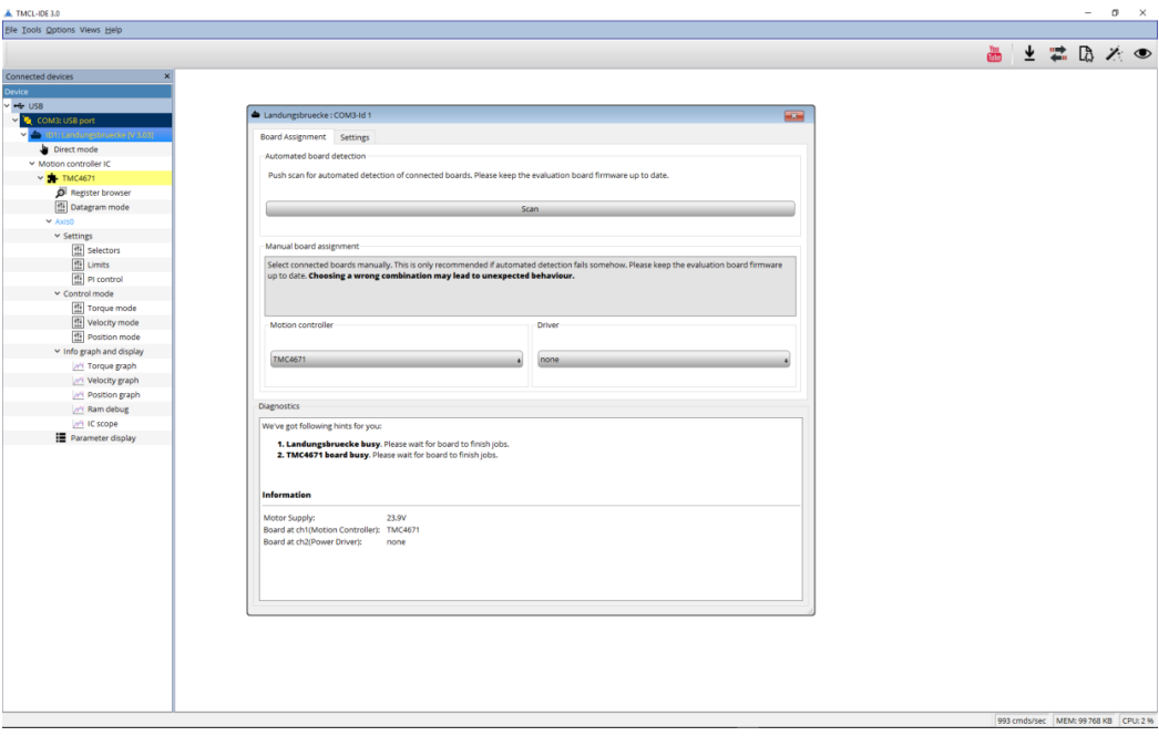
Start TMCL-IDE Wizard – Click the Weasel


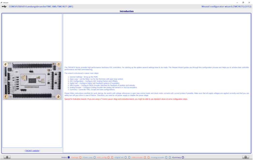
TMCL-IDE Wizard – Introduction

TMCL-IDE Wizard – Main Settings – Set Defaults for DC Motor

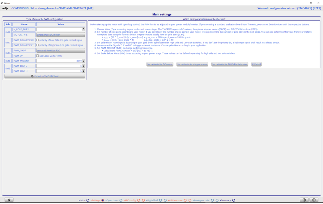
Set Number of Pole Pairs = 1 for possible later use of encoders.
TMCL-IDE Wizard – Open Loop Settings


Use UQ_EXT to set the PWM duty cycle for the DC motor to run it open loop. Start with small values. The range of UQ_EXT is -32767, …, 0,…, +32767 associated with PWM duty cycle -100%, …, 0%, …, +100% where -100% stands for negative supply voltage and +100% stands for positive supply voltage.
For initial ADC setup set UQ_EXT = 0 and use a coil with inductance L[mH] resistance R[Ohm] according to your DC motor or block your DC motor so that it does not turn. With that, one can set up the current measurement and the PI closed loop current control.
TMCL-IDE Wizard – ADC Selection


Set ADC_I0_SELECT = ADC_SD_I0_RAW, set ADC_I_UX = UX, and load Sigma Delta Defaults.
TMCL-IDE Wizard – ADC Configuration

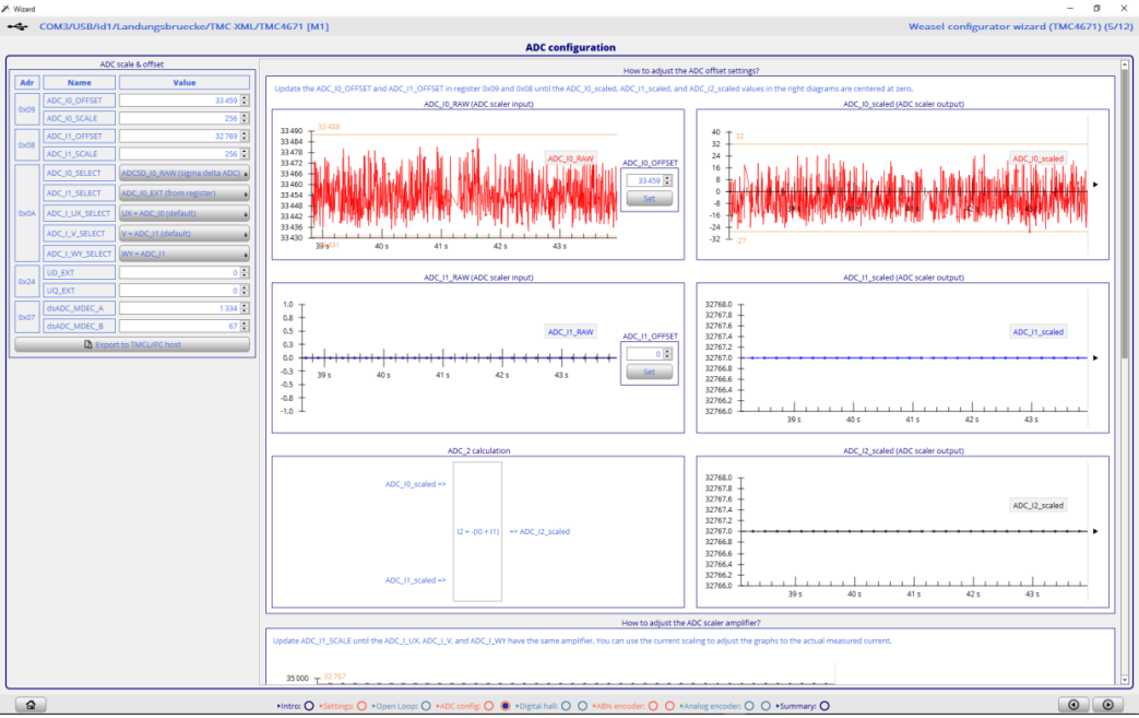
Set ADC_I0_OFFSET for ADC_I0_SCALED.
TMCL-IDE Wizard – ADC Configuration – Check Current Scaling


Set UQ_EXT = 1000 and UQ_EXT = -1000 and observe ADC_I0_SCALED and check for correct sign. The sign is correct if a positive voltage UQ_EXT causes a positive current ADC_I0_SCALED.
TMCL-IDE Wizard – Encoder Test Drive (Torque Mode)


Set Defaults and Start. Toggle PID_TARGET -500 and +500. Then switch PWM = OFF and disconnect the coil respectably the blocked DC motor and connect the DC motor. Increase the absolute value of PID_TARGET if the target current is too low to turn your DC motor.
To turn a DC motor in torque mode, there is no need for an encoder. To turn DC motor in velocity mode or in position mode, an encoder is required. For a DC motor, the encoder setup is easier compared to the encoder setup for the FOC.
Author
