Objective
The objective of this activity is to build a simple tilt sensor using the ADXL327 and observe how the output voltage varies with inclination on x and y axes.
Tilt Sensor Using the ADXL327
Background
Tilt sensors are used for measuring the tilt in multiple axes of a reference plane. These sensors produce an electric signal that is proportional to the degree of inclination with respect to the axes. The tilting position is measured with reference to gravity and enables the easy detection of orientation or inclination.
In this activity we will monitor the tilt in two axes, x and y, using the ADXL327 accelerometer. The functional block diagram of this integrated circuit is presented in Figure 1.


The ADXL327 is a small, low power, complete 3-axis accelerometer with signal conditioned voltage outputs. It can measure the static acceleration of gravity in tilt-sensing applications, as well as dynamic acceleration, resulting from motion, shock, or vibration. The output signals are analog voltages that are proportional to acceleration. The ADXL327 uses a single structure for sensing the x, y, and z axes. As a result, the 3-axis sense directions are highly orthogonal with little cross-axis sensitivity.


Materials
- ADALM2000 Active Learning Module
- Solderless breadboard, and jumper wire kit
- One ADXL327 accelerometer
- Two 0.047 μF capacitors
- One 0.1 μF capacitor
- Two AD8561 comparators
- Four LEDs
- Four 100 Ω resistors
Hardware Setup
Start by building the circuit presented in Figure 1 on a solderless breadboard. The CDC capacitor placed close to the ADXL327 supply pins adequately decouples the accelerometer from noise on the power supply. For most applications a single 0.1 μF capacitor is suitable. Capacitors must be added onto the XOUT and YOUT pins to implement low-pass filtering for antialiasing and noise reduction. Refer to the data sheet of the ADXL327 to see how to choose the values of these capacitors. For this application, 0.047 μF filter capacitors can be used. The breadboard connections are presented in Figure 3.


Procedure
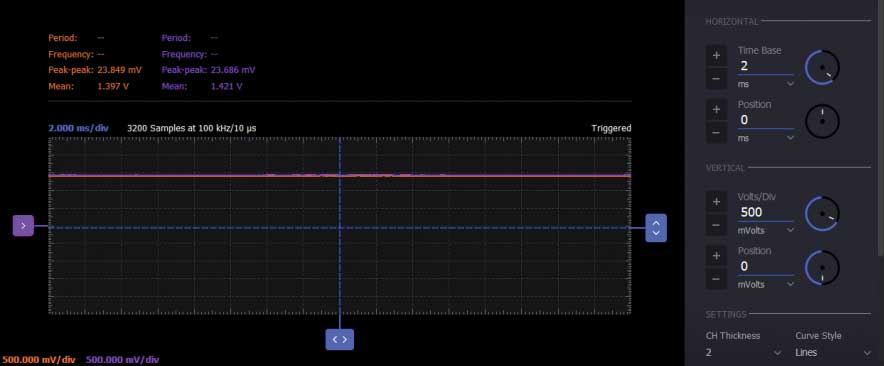
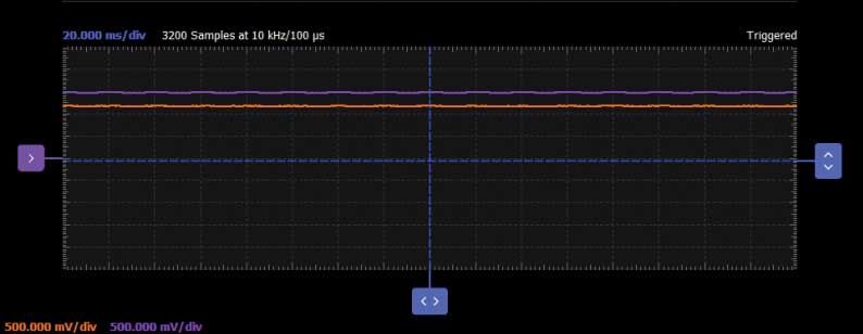
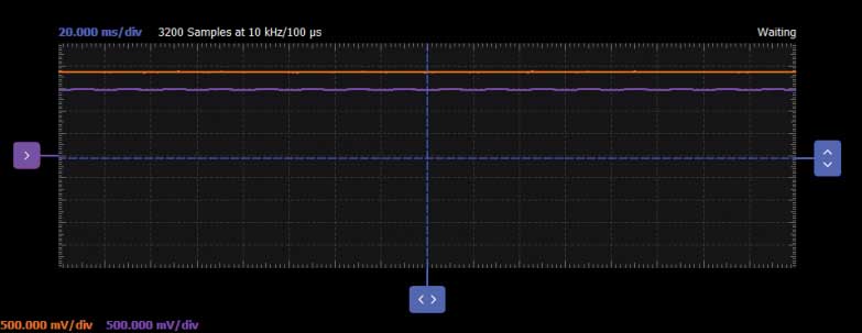
Turn on the positive power supply at 3 V and monitor XOUT on Channel 1 of the oscilloscope and YOUT on the Channel 2. The zero g bias output is nominally equal to VS/2 at all supply voltages. In this case you should see an offset signal at around 1.5 V. If you tilt the breadboard at different angles on x or y axes, the output voltage will increase or decrease proportionally with the movement sensed.
Tilt Sensor with LED Indicators
Background
We monitored the output voltage of the ADXL327 accelerometer on the oscilloscope. Using the AD8561 comparators and LEDs is possible to make the tilt sensor send light signals when the the degree of inclination changes or when a vibration is sensed. We use one AD8561 comparator for each axis. The zero g bias output is similar on both axes and will be the reference of both comparators. On each of the two outputs of the comparator, an LED will be connected. The two output signals are opposite so only one LED will be active at a time.

Hardware Setup
On the solderless breadboard you will add two comparators and two LEDs (with the corresponding current limiting resistor) for each output of the accelerometer. In Figure 5 you can see the circuit schematic and the breadboard connections are shown in Figure 6.


Procedure
In this case we need the power supplies V+ and V- set at ±5 V for the two comparators. The signal generator Channel 1 (W1) will be set to a constant 3 V waveform and used as VS for the ADXL327. The second channel of the signal generator (W2) will be the reference input of the comparators. Its value must be set approximately equal with the zero g output bias. This value was previously measured for the two accelerometer outputs (Figure 4). In this way, every time a change of tilting degree is sensed and the voltage varies, the comparators outputs will change their state, turning the LEDs on accordingly. Since the oscilloscope has only two channels available, we can analyze one output voltage of the accelerometer at a time, but the LEDs will be on and will signal the changes in both x and y axes. XOUT is connected to Channel 1 and the reference voltage generated with W2 is connected to Channel 2.


If you tilt the breadboard to the right on x-axis, the input voltage of the comparator will go below the reference voltage so the /OUT pin will be high, turning its corresponding LED on.

If the tilt is in the opposite direction, to the left, the input voltage of the comparator is higher than the reference turning high the OUT pin and the LED connected to it.

Questions:
- How will CDC influence the circuit if its value is changed?
- Why should the user limit the bandwidth and what are the criteria for band limiting XOUT, YOUT, and ZOUT?
You can find the answers at the StudentZone blog.


