Are you new to ADCs? Does working with a complex system with multiplexer, PGA, buffer, Σ-Δ converter, VREF, and power supply feel overwhelming and make you question where to start? That is where Virtual Eval becomes beneficial. Change the analog input of an ADC, the gain of a PGA, the voltage reference, or the power, and see the impact on step response, H(f)response, or the converter histogram.
The first member is the AD7124-8 virtual eval board.
Why Virtual?
The performance of a design is defined by the individual products selected for the application. While product data sheets provide the first hints and input about performance, evaluation boards will typically be used to better characterize the complete design of the respective circuit. They allow for the direct testing of products like converters, amplifiers, and insulators. Nevertheless, evaluation boards have a crucial disadvantage. They need to be ordered and connected to measuring instruments, and when testing a variety of boards to find the optimal configuration, the process can become especially time and cost intensive. To avoid this complexity, Analog Devices developed the online tool, Virtual Eval, which allows designers to evaluate converters using a simulation. The tool helps avoid material costs and also can save essential time in the preselection phase of a design.
Virtual Eval accesses an updated and comprehensive database of Analog Devices converters. While on the one hand the respective environment of the converter can be accurately simulated, on the other hand it can be tested in various scenarios and in boundary conditions. In Figure 1, the different options and usage of the tool are explained using the AD7124 analog-to-digital converter (ADC). The AD7124 is a 24-bit, Σ-Δ converter with an additional expanded repertoire of diagnostic options—for example, the detection of cable connections or shorts.

As a first step, Virtual Eval allows users to view the complete block diagram of the converter (Figure 1). By directly clicking on the respective internal module, its parameters can be adapted to match the desired simulation scenario. Adjustable modules are, for example, the input amplifier or various switches. The options available are also displayed in settings on the left side of the screen. In case of the AD7124, further adjustable options include the settings of the filters in SINC4 + 1 or SINC4, the internal clock, and the voltage reference. Other possible calibrations are the conversion rate or timing.
With all the parameters set, the properties of the converter can be visualized and evaluated. First, it is possible to display the input waveform (Figure 2a). In addition, it is possible to calculate the fast Fourier transform (FFT) of the input signal. The histogram (Figure 2b) allows users to determine the statistics and also accuracy of the converter.

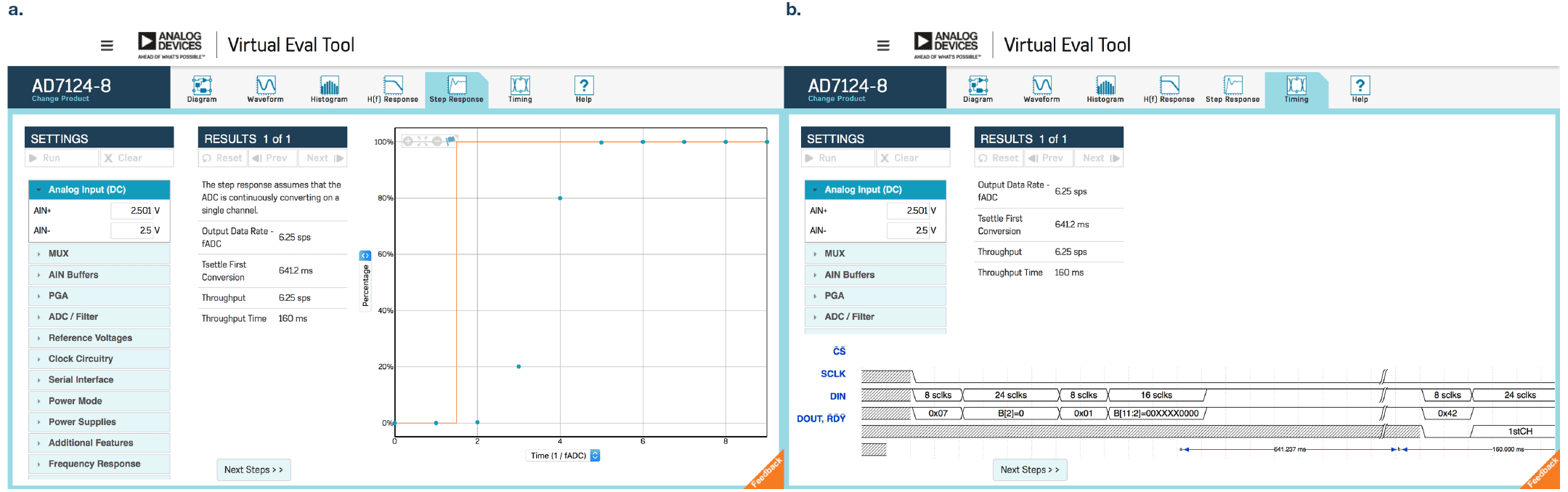
Second, Virtual Eval also displays the frequency response curve and step function of the signal (Figure 3a). In general, the converter is chosen to match the Nyquist criterion. Using the step function, it is possible to calculate an exact value for the maximum input frequency, including a safety margin. The rise of the step function can only be resolved with a suitable conversion rate for the ADC—if the conversion rate is insufficient, data will be lost. Finally, the timing diagram shows the response of the AD7124 over time (Figure 3b), allowing the simulation of various scenarios, like reduced current consumption or a raised conversion rate.
Conclusion
The Virtual Eval simulation tool of analog-to-digital converters provides a simple way to simulate various ADCs in different conditions and scenarios. Not only is it a cost-saving process, it also shortens the selection process remarkably, allowing designers to choose a suitable converter without evaluation boards and expensive tests. As soon as the converter of choice has been identified, it can be found on the help page of the tool, containing its data sheet and further information. In the near future, the database will be expanded on integrated modules, including, for example, AMR sensors with an integrated converter.
Quiz
What would happen with the AD7124-4, when the programmable gain amplifier is set to 128 and the differential input voltage to 0.1 V (tip: what is a differential input?). The reference voltage is set to 2.5 V, power supply: AVDD = 3.3 V, IOVDD: 2.7 V (everything else keeps the standard settings).
Please calculate yourself and simulate in the Virtual Eval Tool.
The answer of this question you will find at the StudentZone.
