Today, handheld personal digital assistants (PDAs) are popping up just about everywhere. They are finding favor, not only with busy executives, but also with mainstream consumers—and even in the classroom! Their ease of use and portability have been keys to their rapidly growing success. The most popular examples include the Palm Pilot series, the Handspring Visor, and the Sony Clie. It is estimated that this year alone some 15 million PDA units will be sold worldwide, with annual sales expected to grow to 34 million units by 2004. A common feature of all of these PDA units is their method of entering data via a stylus and a resistive touch screen. With it the user can easily enter dates in his/her diary, send email, keep shorthand minutes of meetings, etc.
The touch screen itself is typically a 4-wire (±X and ±Y) resistive element. There are also 5-wire resistive screens and capacitor screens on the market, but they are typically more expensive. The touch screen interfaces with the host microprocessor via an A/D converter (ADC), such as the AD7873 and AD7843, which have special features tailored to the application. This article will discuss the common application issues faced by designers when interfacing an ADC to a resistive touch screen, and how they are solved with the AD7873.
Theory of Operation and Details of the Application
The touch screen usually consists of two layers of transparent resistive material—usually indium tin oxide (ITO) or some other form of resistive polyester material, with silver ink for electrodes. The total resistance of each layer varies from vendor to vendor, but typical screens are in the 100 to 900-ohm range. The two layers are stacked on an insulating layer of glass, separated by tiny spacer dots. They are interfaced electrically to a controller A/D converter. Figures 1 and 2 show, in simplified form, how a controller ADC might interface with a 4-wire resistive screen.

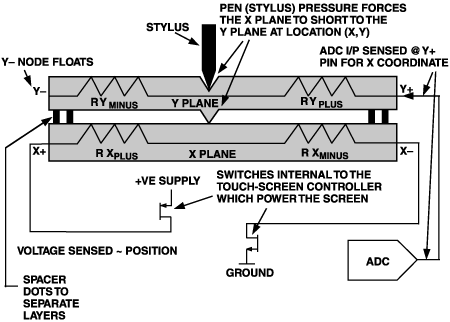
During measurement of a given coordinate, one of the resistive planes is powered along its axis through switches on the controller ADC chip, and the other plane is used to sense the location of the coordinate on the powered plane. For X coordinate measurement, the X plane is powered. The Y plane is used to sense where the pen is located on the powered plane as follows: At the location where the pen depresses the touch screen, the planes are shorted. The voltage 'picked up' on the sensed plane is proportional to the location of the touch on the powered plane. This voltage is then converted using the controller's ADC.
For a Y-coordinate measurement, power is applied to the Y plane, the X plane is used to sense the position, and the voltage is digitized. The digital code corresponding to the X and Y coordinates is then operated on by the host microprocessor, and the command, information, or instruction intended by the stylus location is registered.
Basic AD7873 touch-screen interface
Figure 3 illustrates a simplified block diagram of the AD7873. In addition to serving as a coordinate-measurement transducer, it provides a number of peripheral functions important for the PDA's function, including measurements of temperature and battery condition, touch detection, and pressure measurement—plus an on-chip 2.5-V voltage reference.
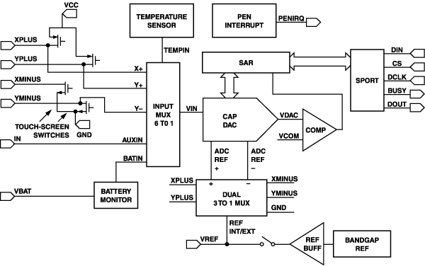
Figure 4 illustrates a typical application diagram for the AD7873 interfacing with a 4-wire resistive touch screen. First let's discuss the basic functionality—stylus coordinate measurement. The set of touch-screen switches at the left in Figure 3 drive the resistive screen via the so-called tablet pins, X+, Y+, X-, and Y-. The tablet pins also serve as sensors of position voltage from the screen when not active, in applying the method of interfacing described briefly above.

A number of things were considered in the implementation of the design. First, the switches must be able to source and sink current to/from the low impedance screen. Say, for example, the supply is 5 V and the screen impedance is 200 ohms. The p-MOS switches to the positive supply (on the X+ and Y+ pins) must be able to source 25 mA when the screen is powered for coordinate measurement. Similarly the n-MOS switches to ground (these are on the Y- and X- pins) must be capable of sinking this 25 mA. The switches' drain and source connections must be carefully designed at the layout stage to avoid electromigration problems (due to the large current density in these nodes). The conservatively designed AD7873 switches are capable of supplying a 70-ohm screen, using a 5-V supply.
The on-resistance of the switches, about 6 ohms, also posed a challenge. For example, when used with screen impedances as low as 100 ohms and a minimum supply voltage of 2.7 V, the voltage drop across the switches is appreciable and greatly reduces the dynamic range of signals applied to the converter input. To avoid a corresponding reduction of conversion accuracy and effective resolution, and because the ON resistance of the switches may not track the resistance of the screen over temperature and supply, the converter must be able to operate in a ratiometric mode. Figures 5 and 6 illustrate respectively how the AD7873 can be configured in both ratiometric and single-ended modes of operation for coordinate measurements.
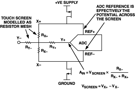

Using the ratiometric mode, the actual ADC reference is taken from the drain nodes of the switches powering the screen. For example, if a Y coordinate is being measured, the Y plane is powered and the REF+ and REF- of the ADC are taken from the Y+ and Y- pins, respectively. The A/D conversion will be ratiometric; i.e., the result of the conversion will be equal to the ratio of touch-screen resistance at the measuring point to the total touch-screen resistance, irrespective of the voltage drop in the AD7873's switches. This is the best way of ensuring the accuracy of coordinate measurements.
But there is a trade-off: In ratiometric mode, the screen must remain powered during the actual conversion process, in addition to the acquisition phase, since the screen voltage is used as the ADC reference. Alternatively, during a single-ended conversion, the screen need only be powered during the acquisition of the input signal. For the AD7873 this requires 3 clock cycles, at worst 20% of the overall conversion time (assuming a 15 clocks-per-conversion mode—which is the device's fastest valid throughput rate). However, used ratiometrically, at this fastest rate, the screen will be permanently powered while the device is on. If the screen resistance is 100 ohms and a 5-V supply is used, the screen will draw 50 mA—an obvious consideration in battery-operated handheld devices.
With this dilemma in mind, the AD7873 has been designed to offer the designer a choice of four power down options to better manage the overall power consumption of the touch-screen controller, using the device's 2-bit selective power-down option control.
Power down bit setting
00. Full power down between conversions. Both the ADC and the internal reference are powered down between conversions. If the ratiometric mode is selected, the touch-screen drivers will be turned off between conversions (for cycles longer than than 15 clocks).
01. The ADC remains on between conversions, but the reference powers down. (An external reference may be used.) The touch screen power is switched off between conversions, as in mode 00.
10. The ADC powers down between conversions, while the internal reference remains on. This is useful, as the reference requires about 7 µs to power up. So when doing single-ended measurements (such as battery and temperature readings) with the internal reference, there is no need to allow a delay for the reference to power up. The touch screen power is switched off between conversions, as in mode 00.
11. The ADC and internal reference remain powered on between conversions. In this mode, the switch drivers to the touch screen will remain on until the selected input channel or power-down mode is changed, or until CS (convert start) is brought high.
Whatever option is used, the designer must realize that the bulk of the power will be dissipated in the external touch screen when it is powered. The AD7873 itself will dissipate only about 2.4 mW with the internal reference enabled, a 2-MHz data clock, throughput of 125 kSPS and with a 3.6-V supply—while a 100-ohm screen is dissipating 129.6 mW! So the converter dissipates less than 2% of the power dissipated in the screen. However, it should be noted that in the first 3 of the 4 cases listed above, the screen-drive switches can be turned off between conversions. This feature is useful for providing a considerable reduction in average screen power if the application can allow for a reduced throughput rate (with the clock frequency held at 2 MHz).
The first three power-down options above will be especially helpful. For example, using those options, a throughput rate of 20 kSPS would reduce the screen power to an average of 20 mW under the conditions described above. For character recognition from the screen, throughput rates of 20 kSPS may be acceptable without any discernable reduction in performance. In general, however, a response-speed tradeoff should be anticipated. The screens themselves may have large parasitic capacitance associated with them—10 nF is not uncommon. This may result in a non-negligible R-C time constant, so that time must be allowed for settling before screen measurements can be taken. For this reason, in many circumstances, powering down the screens between conversions might not be such a good idea—unless steps are taken to account for the large screen R-C time constant (this will be discussed later).
Resolution of the converter itself needs to be in the 10- to 12-bit range for typical screens. The AD7873 provides 12 bits of resolution. The B grade guarantees 12-bit no-missing-code (NMC) performance, while the lower-cost A version provides 11-bit NMC.
Peripheral functions—battery, temperature, and pressure measurement: The AD7873 supports a number of important peripheral functions vital to the PDA:
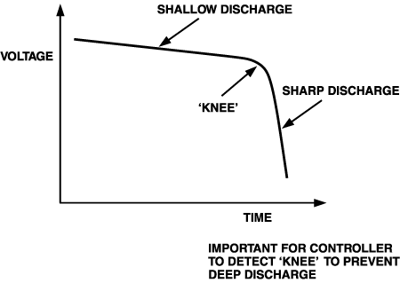
A dedicated battery-monitoring ADC channel consists of an attenuator circuit that divides down the unregulated battery supply voltage by 4 and digitizes it. A supply of up to 6 volts can be applied to the VBAT input pin. The accuracy of the function is important in applications that use battery supplies with a very shallow discharge slope and a very sharp knee (e.g., Li-ion batteries), so it's important for the system to know where the battery is in its discharge profile at any given time. Usually, the microprocessor instructs the battery channel to digitize the battery voltage every few seconds. Should the battery enter the sharp discharge part of its curve (Figure 7), it could be damaged and not recover from such a 'deep discharge' event. In practice, typical PDAs will flag a condition well before the knee is reached and respond appropriately. The AD7873 battery channel will give typical accuracy performance in the 0 to ±1% range with worst case error of ±3%, using the internal reference. Where better accuracy is required, the user may need to calibrate this reading, depending on the battery's discharge characteristic.
Temperature measurement is the second important peripheral function performed by the AD7873. Temperature within the PDA's case is an especially important parameter to monitor in devices containing rechargeable batteries. Typically, if the temperature exceeds 45°C during charging, the microprocessor needs to be flagged and provide an appropriate action to avoid permanent damage to the PDA due to overheating. Figure 8 shows the scheme used to measure temperature.

The AD7873 provides two modes of temperature measurement. The first, the single-conversion method, performs a simple conversion of the junction voltage of a diode-connected PNP transistor, biased with a constant current. The diode voltage will vary with temperature by about -2.1 mV/°C. Typically the reading would be factory-calibrated at 25°C during manufacture of the PDA. This method will typically provide a resolution of about 0.3°C with an accuracy of ±2°C.
To avoid calibration by the PDA manufacturer, a second—differential—method is provided on the AD7873. Two conversions are required, Temp 0 and Temp 1. Temp 0 is performed with a low value of diode bias current, I0, and Temp 1 is performed with a bias current, I1=105 I0. From the Ebers-Moll equation and using some simple math, we can show that:
EQUATIONwhere
k=Boltzmann's constant,1.38054×10-23eV/K
q= Charge on the electron, 1.602189×10⁻¹⁹ C
T= Absolute temperature in kelvins
N= I1/I0, typically 105, as suggested for the AD7873.
Hence
T (degrees C) = 2490 × ΔVbe - 273 K
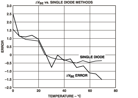
Because ; ΔVbe is limited to about 142 mV, the resolution of the differential method is significantly less then that of the single-conversion method. Typical resolution of about 1.6°C is achieved. The accuracy of both methods is typically the same, about ±2°C. Figure 9 plots a typical accuracy comparison for both methods over the temperature range, 0 to 70°C. The main advantage of the differential temperature method is that it eliminates the need for calibration by the PDA manufacturer.
Pressure (or more precisely touch resistance) can be calculated via a number of simple arithmetic manipulations using the AD7873. One can determine whether the touch response is being generated by the stylus or a finger—or some other object—by measuring the contact resistance between the X and Y plates. This provides an indication of the size of the depressed area and the applied pressure. The area of the spot touched is proportional to the touch resistance. Two methods can be used. The first requires the user to know the total resistance of the X plane membrane. The second method requires that the total resistance of both X and Y membranes be known. Equations and diagrams can be found on the data sheet.
Waking up with a touch—the pen-interrupt function.
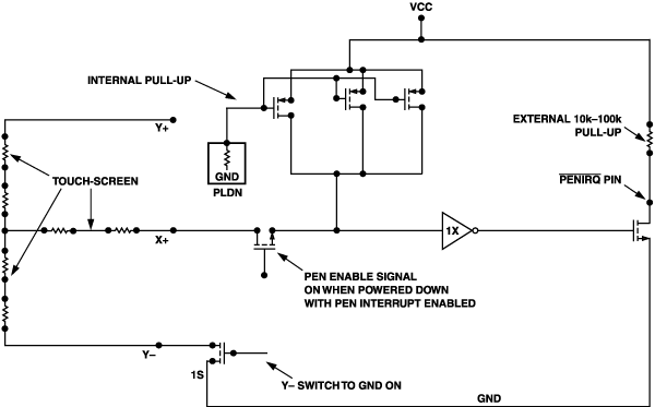
Figure 10 illustrates the pen interrupt function, which provides an active-low open-drain output signal to the host microprocessor. When the part is powered down in a mode where the pen interrupt is enabled, a touch on the screen will cause the voltage on the PENIRQ pin to be pulled to ground. In this mode the Y- pin switch driver to ground is turned on during power down; when the two screens touch, the X+ pin is pulled to ground via the Y- pin—thus initiating an interrupt. The touch-resistance threshold is typically <30 kohms for the AD7873. This level will ensure that spurious interrupts do not occur (if, for example, the screen were accidentally brushed against in a user's pocket). The microprocessor can use this interrupt to wake up the AD7873 and start coordinate measurements. Normally the PENIRQ pin voltage will idle at logic high. An external pull-up resistor in the range 10 to 100°kohms is required on the PENIRQ pin for optimum operation of the function. Implementing this function using an open-drain output ensures that both the rising and falling edges of the PENIRQ signal are sharp, uninfluenced by the touch-screen capacitance (which can be as large as 10 nF) or the screen resistance itself.
Application Issues when interfacing the AD7873 to a touch screen
We've already mentioned the trade off between power consumption in the screen and the time required for the screen to settle before coordinate readings can be taken—as a consequence of the large parasitic capacitance between the plates (about 10nF in some cases). Additional sources of potential error exist. The screens themselves can pick up a lot of noise from the LCD panel and backlight circuitry. The screen can also act as an antenna, picking up noise from external EMI/RFI sources. Mechanical bounce when the screen is touched carelessly is also a potential source of error. In most cases the designer will seek to minimize this noise by installing low pass filters on the tablet pins to ground. Capacitors of the order of 0.01 µF are common. (It's important to note that series resistance is not recommended for these filters, since it would lower the resolution of the converter because of the added voltage drop across the resistor). Because the filter capacitance, parasitic screen capacitance, etc., all act to increase the RC time constant of the screen, it is not advisable to make screen coordinate measurements in single-ended mode. The acquisition time of 3 clock cycles simply may not be long enough to allow the screen to settle before taking readings. For this reason, the ratiometric mode is much better. In that mode, the screen remains powered for the full conversion cycle and, by averaging readings, an accurate result can be obtained—provided that the device be powered up in a mode where the touch-screen switch drivers remain turned on.
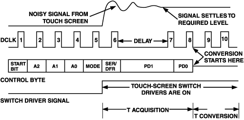
One can also get an accurate result without the need for averaging by simply delaying the acquisition time of the converter by including a delay between either the 6th, 7th or 8th bits of the DIN word, as shown in Figure 12. The above discussion demonstrates the need for the designer to take account of the type of screen used with the AD7873. The converter has enough modes of operation and speed (minimum DCLK frequency is 10 kHz) to do its basic job—accurate coordinate measurement—with the most demanding of resistive touch screens and environments.
Another problem designers may consider is failure due to high-energy voltage spikes discharged from the screen to the converter via the tablet pins. During PDA manufacture, the screen is floating and can build up considerable charge. This charge could eventually discharge through the tablet pins of the converter and permanently damage it. Then, during operation the screen is exposed to the outside world, and ESD events can occur which could damage the converter via the tablet pins—rendering the entire PDA useless. The AD7873 includes a silicon controlled rectifier (SCR)-based protection scheme at the tablet pins to make these I/Os as robust as possible against damage from ESD events. The ESD structure is capable of 15-kV protection—an attractive feature for PDA manufacturers, reducing risk of failure in the field—as well as during manufacture itself.
Summary
The AD7873 facilitates coordinate measurement from a 4-wire resistive touch screen, meeting well the particular requirements of interfacing an ADC controller chip to the touch screen. Besides the basic coordinate measurement, the AD7873 provides the designer with battery monitoring, temperature sensing, touch detection, and pressure-measurement functions. We've also discussed issues designers can face when designing such systems—including power consumed by the screen, touch-screen settling issues and potential ESD damage. The reader should now have a good insight into how the key circuitry of a PDA works, and an appreciation for the complex nature of the designer's task—and how a well-designed integrated-circuit chip can make it easier.

