Accelerometer Specifications - Quick Definitions
Accelerometer Specifications - Quick Definitions
Measurement Range:
The level of acceleration supported by the sensor’s output signal specifications, typically specified in ±g. This is the greatest amount of acceleration the part can measure and accurately represent as an output. For example, the output of a ±3g accelerometer is linear with acceleration up to ±3g. If it is accelerated at 4g, the output may rail. Note that the breaking point is specified by the Absolute Maximum Acceleration, NOT by the measurement range. A 4g acceleration will not break a ±3g accelerometer.
Accelerometer Sensitivity:
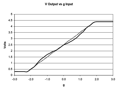
The ratio of change in acceleration (input) to change in the output signal. This defines the ideal, straight-line relationship between acceleration and output (Figure 1, gray line). Sensitivity is specified at a particular supply voltage and is typically expressed in units of mV/g for analog-output accelerometers, LSB/g, or mg/LSB for digital-output accelerometers. It is usually specified in a range (min, typ, max) or as a typical figure and % deviation. For analog-output sensors, sensitivity is ratiometric to supply voltage; doubling the supply, for example, doubles the sensitivity.
Sensitivity change due to Temperature is generally specified as a % change per °C. Temperature effects are caused by a combination of mechanical stresses and circuit temperature coefficients.
 |
| Figure 1. Nonlinearity is a measurement of the deviation of an accelerometer response (illustrated in black) from a perfectly linear response (in gray). This graph is for illustration purposes only and does not show real accelerometer data. |
Nonlinearity:
Ideally, the relationship between voltage and acceleration is linear and described by the sensitivity of the device. Nonlinearity is a measurement of deviation from a perfectly constant sensitivity, specified as a percentage with respect to either full-scale range (%FSR) or ± full scale (%FS). Typically, FSR = FS+FS. Nonlinearity of Analog Devices accelerometers is low enough that it can most often be ignored.
Package Alignment Error:
The angle between the accelerometer-sensing axes and the referenced package feature (see Figure 2). "Input Axis Alignment" is another term used for this error. The units for package alignment error are "degrees." Packaging technology typically aligns the die to within about 1° of the package.
(Orthogonal) Alignment Error:
The deviation from the ideal angular displacement (typically 90°) between multi-axis devices (see Figure 2). Analog Devices accelerometers are manufactured using photolithography on a single piece of silicon, so axis-to-axis alignment error is not generally a problem.
Cross-Axis Sensitivity:
A measure of how much output is seen on one axis when acceleration is imposed on a different axis, typically specified as a percentage. The coupling between two axes results from a combination of alignment errors, etching inaccuracies, and circuit crosstalk.
Zero-g Bias Level:
Specifies the output level when there is no acceleration (zero input). Analog sensors typically express this in volts (or mV) and digital sensors in codes (LSB). Zero-g Bias is specified at a particular supply voltage and is typically ratiometric with supply voltage (most often, zero-g bias is nominally half the supply voltage).
Several aspects of zero-g bias are often specified:
- Zero-g Voltage, in V, specifies the range of voltages that may be expected at the output under 0g of acceleration.
- Output Deviation from Ideal, also called Initial Bias Error, is specified at 25°C, either in terms of acceleration error (g) or output signal: mV for analog sensors and LSB for digital sensors.
- Zero-g Offset vs. Temperature, or Bias Temperature Coefficient, in mg/°C, describes how much the output shifts for each °C temperature change; and
- Bias Voltage Sensitivity is the change in "Zero-Bias Level" with respect to change in power supply. The units for this parameter are typically, mv/V, mg/V, or LSB/V.
- Zero-g Total Error includes all errors.
Acelerometer Noise Density:
In ug/rt(Hz) RMS, is the square root of the power spectral density of the noise output. Total noise is determined by the equation:
Noise = Noise Density * sqrt(BW * 1.6)
where BW is the accelerometer bandwidth, set by capacitors on the accelerometer outputs.
Analog Devices accelerometers' noise is Gaussian and uncorrelated, so noise can be reduced by averaging the outputs from several accelerometers. supply voltage (most often, zero-g bias is nominally half the supply voltage).
Total Noise:
The random deviation from the ideal output and is equal to the multiplied product of the Noise Density and the square root of the Noise Bandwidth. The units for this parameter are typically mg-RMS.
 |
Figure 2. Showing package alignment error α and sensor alignment error θ. α is the angle between the sensor axes and the package axes. θ is the deviation of the sensor axes from orthogonal, i.e., the difference between (ysensor – xsensor) and 90°. |
Output Data Rate:
In digital-output accelerometers, defines the rate at which data is sampled. Bandwidth is the highest frequency signal that can be sampled without aliasing by the specified Output Data Rate. Per the Nyquist sampling criterion, bandwidth is half the Output Data Rate.
In analog-output accelerometers, bandwidth is defined as the signal frequency at which the response falls to -3dB of the response to DC (or low-frequency) acceleration.